What's new
What's new

Best way t make this little crankshaft

Joined
Nov 19, 2007
Location
marysville ohio
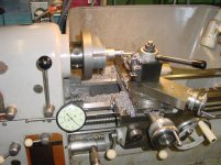
I need to make these in lots of 50. I have been turning all the in line details then putting it in a square 5c collet block and off seting it .197 in a four jaw chuck. Turn the first journal, then I rotate the block 180* and do the other one. The lobes need to be 180* apart with a .0005 tol. on the dia. I use a dial indicator to check the offset. It was OK for a few prototypes but it takes way to long, anybody got any method to speed it up?DSCN1098.jpgDSCN1099.jpg
 
I made some similar shafts a while back. I came in with an endmill in an axial live tool holder and interpolated the first lobe then jumped over and did the second lobe. In order to do this you need to make sure the top of the flutes are square and there is minimal rad on the shank. I turned the backside eccentric shaft with a parting tool and was a one shot deal.
 
I made some similar shafts a while back. I came in with an endmill in an axial live tool holder and interpolated the first lobe then jumped over and did the second lobe. In order to do this you need to make sure the top of the flutes are square and there is minimal rad on the shank. I turned the backside eccentric shaft with a parting tool and was a one shot deal.

OK, now if you had a ancient Miltronics ML20 lathe with no live tools?
 
OK, now if you had a ancient Miltronics ML20 lathe with no live tools?
You send it to my neighbor with a room full of CNC swiss, and he mails you the whole order back in a leetle box...:D

"once and done" drops off complete will make them cheap enough for you to send this job out, mark it up 10%.
 
On a mill or jig bore,make a nest or pot chuck. Bore a blind hole to hold the blanks. In bottom of bore,bore three holes,one on center and two separated by twice the crankpin offset( all on the same diametrical line, of course).

In each hole,set a dowel pin the diameter of the cylindrical pilot on drill-countersink for 60deg center holes.

Drop a blank in, drill/countersink the three holes in one end. Turn blank upside down, dowels will register in holes already drilled, drill the three holes in the other end.

Then you can turn all the features between appropriately concentric or offset centers.. Probably have to turn the offset features first, since turning the end journals may remove the offset center holes.
 
Does this have to have oil passages drilled? how about several pieces then loctite it all together in a jig. What is the service environment.
Bil lD.
 
Its hard to determine what size the item is. Based on the paper towel design, maybe 2" in length?

Normally camshafts are forged, both to make them stronger and to reduce the amount of metal that needs to be removed. I assume that does not apply here and you are able to just hog off all that metal because the item is so small.

Normally camshafts are hardened, therefore, they are only rough turned and the final dimensions are achieved by grinding after hardening. Since your tolerance is 0.0005" I am guessing the customer wants to skip that step as well and use an unhardened camshaft.

Normally camshafts have cams. The item in question appears to have cylindrical pushers. I will assume you are trying to produce circular profiles, not cams. Therefore, we have a cylindershaft, not a camshaft. ;)

To make a lot of them, you will probably want a fixture and it would be a good idea to turn between centers due to the tight tolerances. Unfortunately, making the fixtures will probably take you nearly as much time as manually turning at least 10 of the items in a four-jawed chuck. The basic procedure is as follows.

1. Turn and face two hot rolled disk plates about 3/8" thick of a diameter sufficient to encompass your needed offset radii. Both plates should fit together well with no visible gaps or rocking. They only need to fit on their faces, the backs are irrelevant.

2. Clamp the plates together, and drill and ream 3x 3/8" holes near the perimeter of the plates equally spaced. Since the plates are clamped together the holes will register the two plates perfectly.

3. Bolt the plates together with 3/8" shoulder screws.

4. Turn the rims of the plates, so they are now exactly the same diameter and the TIR is less than 0.0003".

5. Bore 3 holes through the plates corresponding to the 3 circle offsets you want to turn. These holes are all the same size, the size of your journal. The bores must be a nice press fit to the journals, so you will need to lap them. Note that the holes will overlap, that is ok as long as less than about 60 degrees of the circles overlap. If the overlap is too much, like 120 degrees, then you will need to make a another set of plates.

6. (Optional) Drill holes for attaching balance weights, one for each bore so there will be 3 of them. This will allow the spindle to run with no centrifugal pressure.

Your fixtures are complete.

To use the fixtures:

1. Turn the journals on the workpiece so that the runout is less than 0.0003".

2. Mount faceplates in your both your headstock and tailstock and make sure they are well-aligned.

3. (Optional) Bolt on your counterweights if you decided to do that.

4. Mount the workpiece in the headstock-side fixture either by using an arbor press or by freeze-warming it and tapping it in. Using a press will be much faster.

5. Use pins through your clamping holes to align the tailstock fixture and press the workpiece into that fixture.

6. Mount the fixtures onto your faceplates by bolting them through the clamp holes with shoulder screws.

7. Check the runout at the rims of your fixtures and on the shoulders of the workpiece. If everywhere you have less than 0.0003" of runout, you are good to go. (Obviously, you need a well-adjusted lathe for this to be possible.)

8. Repeat the same steps for the other 2 holes.
 
You can refine your original process to include a square pot chuck collet with closer ring, for grabbing the square collet block in which the part is held. But that will not be as accurate as dialing in the 4J every move. Your original block must be "perfect" and the collet must be high precision version. Then the square deep collet you make has to be near perfect as well. The process works, but there are 3 levels of stack tolerance: Original collet in block, block in square socket, and deep bore pot chuck collet to closer ring. I think a collet block would fitt fine in a 3" deep chuck, maybe even a 2". Or get a smaller straight shank ER collet chuck to hold the part, and grind the shank square, dead on center; and use it in a regular 5c E-collet if there is enought room for the offset? (to machine a square off set of sufficient size). That would remove one level of stack tolerance. Otherwise back to the deep pot chuck and closer.

This is a 5/8" square collet with about 1/8" off set that I made; but IIRC I may have had to bevel one edge of the work "a small amount" to clear the back of the collet. Could have roughed it out for clearance with a dremel/die grinder, but for me the slight bevel was a plus on the finished part.

smt-squarecollet2.jpg


I did not need the precision you expect, but these are examples of creative use of pot chucks for a set of offset turnings including some that are timed. :) For your app, I would machine the deep collet itself, not use inserts, as that adds yet another stack level if you already have the insert of the collet block.

smt5cworkholding.jpg


smt
 
Fixture all the way, baby. It will pay off the time spent building it many times over.

Here is one I made to do two-throw crankshafts. It is based on a cheap Asian D1-3 chuck backplate blank. The block on front is doweled to it, and can be located left, middle, or right, depending on which journal I am turning. The crank blanks are pulled into the cylindrical spud on the block from the rear using a nut and thread on one end of the nascent crank. The is a small dowel to drive the blanks via a milled notch to keep them from slipping. The setup was nice and stiff, and I made sure the setup stayed stiff by working the outermost journal first, and working may way toward the headstock. The material was LaSalle Fatigue-Proof (higher-strength Stress-Proof or 1144), so not prone to warp.

DSC00002.jpgDSC00008 (1).jpgDSC00009 (1).jpgDSC00032.jpgDSC00036.jpg
 
Its hard to determine what size the item is. Based on the paper towel design, maybe 2" in length?

Normally camshafts are forged, both to make them stronger and to reduce the amount of metal that needs to be removed. I assume that does not apply here and you are able to just hog off all that metal because the item is so small.

Normally camshafts are hardened, therefore, they are only rough turned and the final dimensions are achieved by grinding after hardening. Since your tolerance is 0.0005" I am guessing the customer wants to skip that step as well and use an unhardened camshaft.

Normally camshafts have cams. The item in question appears to have cylindrical pushers. I will assume you are trying to produce circular profiles, not cams. Therefore, we have a cylindershaft, not a camshaft. ;)

To make a lot of them, you will probably want a fixture and it would be a good idea to turn between centers due to the tight tolerances. Unfortunately, making the fixtures will probably take you nearly as much time as manually turning at least 10 of the items in a four-jawed chuck. The basic procedure is as follows.

1. Turn and face two hot rolled disk plates about 3/8" thick of a diameter sufficient to encompass your needed offset radii. Both plates should fit together well with no visible gaps or rocking. They only need to fit on their faces, the backs are irrelevant.

2. Clamp the plates together, and drill and ream 3x 3/8" holes near the perimeter of the plates equally spaced. Since the plates are clamped together the holes will register the two plates perfectly.

3. Bolt the plates together with 3/8" shoulder screws.

4. Turn the rims of the plates, so they are now exactly the same diameter and the TIR is less than 0.0003".

5. Bore 3 holes through the plates corresponding to the 3 circle offsets you want to turn. These holes are all the same size, the size of your journal. The bores must be a nice press fit to the journals, so you will need to lap them. Note that the holes will overlap, that is ok as long as less than about 60 degrees of the circles overlap. If the overlap is too much, like 120 degrees, then you will need to make a another set of plates.

6. (Optional) Drill holes for attaching balance weights, one for each bore so there will be 3 of them. This will allow the spindle to run with no centrifugal pressure.

Your fixtures are complete.

To use the fixtures:

1. Turn the journals on the workpiece so that the runout is less than 0.0003".

2. Mount faceplates in your both your headstock and tailstock and make sure they are well-aligned.

3. (Optional) Bolt on your counterweights if you decided to do that.

4. Mount the workpiece in the headstock-side fixture either by using an arbor press or by freeze-warming it and tapping it in. Using a press will be much faster.

5. Use pins through your clamping holes to align the tailstock fixture and press the workpiece into that fixture.

6. Mount the fixtures onto your faceplates by bolting them through the clamp holes with shoulder screws.

7. Check the runout at the rims of your fixtures and on the shoulders of the workpiece. If everywhere you have less than 0.0003" of runout, you are good to go. (Obviously, you need a well-adjusted lathe for this to be possible.)

8. Repeat the same steps for the other 2 holes.
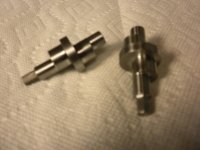
Where did you get "camshaft". The title says "crankshaft" It is 2.35 long, main journals are .393 dia. The 2 offset journals are .590 dia. Projected 5 year volume is less than 1000. No chance they will forge them. I think a lathe with live toys is the way to do it.
 
Fixture all the way, baby. It will pay off the time spent building it many times over.

Projected 5 year volume is less than 1000. No chance they will forge them. I think a lathe with live toys is the way to do it.

I think live tooling is overkill at the predicted volume spread-out over 5 years.

Your use of a collet block offset in a 4-J is half-way home to a fixture approach similar to wot RK used.

Mebbe $200-300 invested to go the next step. Store it all properly 'til next batch is ordered. Should beat present setup on cost & thruput, beat live toys on investment cost to be amortized.

Now .. if you have (enough, certain..) OTHER work to justify the general-purpose live tool up...

Or JF feel like yah wanna add it to the arsenal...

:)


Bill
 
Might making a dedicated face plate be worth the effort? Having the long end of the center shaft in an offset close fit bore and using the square drive as the locator for the 180 flip. The advantage would be a fast set–up and 180 flip. It could be a collect holding bore or just a very good fit. An adjust true to the face plate might be good also.
This to make an accurate quick set up as you might indicate the face and the OD of the face plate to be sure the off sets were correct and square to the main shafts.
I was also thinking about bearinged end caps with having locating flats so the part would run between centers but the end caps in place and the part turning with a belt to the OD but that would be better served with grinding the part.

[with a .0005 tol. on the dia.] likely they want the square if the off sets very good as well.

yes 1000/50 is only 20 setups
 
Fixture all the way, baby. It will pay off the time spent building it many times over.

Here is one I made to do two-throw crankshafts. It is based on a cheap Asian D1-3 chuck backplate blank. The block on front is doweled to it, and can be located left, middle, or right, depending on which journal I am turning. The crank blanks are pulled into the cylindrical spud on the block from the rear using a nut and thread on one end of the nascent crank. The is a small dowel to drive the blanks via a milled notch to keep them from slipping. The setup was nice and stiff, and I made sure the setup stayed stiff by working the outermost journal first, and working may way toward the headstock. The material was LaSalle Fatigue-Proof (higher-strength Stress-Proof or 1144), so not prone to warp.

View attachment 183101View attachment 183102View attachment 183103View attachment 183104View attachment 183105

NICE, Thats just the sort of thing I was looking for. I was thinking of dove tail ways to move the part on the face plate but I like the pins better. Thanks for going to the trouble to post for me.
 
Why did the photos end up like that?

Moonlight: I think you are asking about the out-of-focus in the pics. Try using a tripod and lay a piece of news print next to the parts to check focus. I have to use something like a tripod or mine are worse than what you got. Also, lay a scale or coin next to the subject to give an idea of scale. Good luck.

JH
 
The face plate bushing fixture I mention would be like rklopp shows. I had a friend who did all kinds of jobs on a round magnetic chuck. Think rkiopp's very good and a face plate with screw hole for mounting fixtures also very good.
Still you would have out of balance to contend with.. not so much a problem with grinding such a part.


Back
Top