What's new
What's new

Chamfer vs Edge Condition on drawings (ISO)

BitMag

Plastic
Joined
Nov 29, 2016
Hello,

When dimensioning a chamfer on a parts drawing, according to ISO, one has to show the height of the chamfer and the angle of the chamfer (e.g 0,3x45°). And I think it`s quite similar in ANSI too. When the chamfer has to be toleranced, then one has to add the allowed deviation (e.g 0,3±0,2x45°).

But according to ISO 13 715 there is also something called Edge Condition. This allows to determine the shape of parts edges and corners.

The basic premise between those two methods is similar. So does anyone have good guess, when to prefer on method over the other, when the objective is to dimension and tolerance a chamfer?

I made a schematic, which shows both methods:
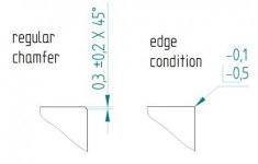
edge cond.jpg

Best regards
 
Never seen anybody use a dimensioned edge condition callout, personally. Chamfer notes are typical where it's a critical feature... Notes re: "break sharp edges" are common for overall edge condition as well.

Inversely, an edge condition I have seen called out, is to keep a sharp edge on a specific corner (usually with the requirement it should be "free of burrs")

I`ve seen some drawings.. The mentioned standard allows dimensioning and inter alia also asymmetrical dimensioning (the chamfer is asymetric).
 
General notes should cover all non-critical edge conditions, IMO, in an effort to declutter drawings. However, I never work to ISO drawing standards, so take that for what it's worth.

Only when an edge condition is considered a major or critical feature should it be directly defined and toleranced. This draws attention to the exceptional edge break situation, as well as preventing unnecessarily redundant callouts.

It also prevents the situation where you really don't care if it's a chamfer or a radius/fillet. All you care is the prevention of sharp edges and burrs, typically. Size can matter. Form usually doesn't. "Break all sharp corners, .03 max" or reference a standard or something. ISO has a fucking standard for everything, it seems. I think I recall seeing one for edge breaking but I wouldn't reference it in my context. I can't expect people to know it.
 
One the first day of my machining traineeship in a machining subcontractor company (in Estonia, EU), when I got the see the very first drawing, it had all sorts of edge conditon requirements on it. In engineerig school this particular subject was totally neglected so I was quite puzzled about it. The drawings originated from a global windturbine corp called Vestas.
So anyway, perhaps some experienced designer can shed some light on this matter..
 
Well yes I can refer to ISO 2768, but still the question stated in my original post is more general. I want to know, when is it useful to use the dimensioned edge condition call-outs?
 
Well yes I can refer to ISO 2768, but still the question stated in my original post is more general. I want to know, when is it useful to use the dimensioned edge condition call-outs?

The answer is unfortunately as general as your question.

There are many things that can decide preference in edge condition.

There may be a desire to avoid sharp edges when plating or painting. Paint/coatings can have a tendency to 'pull back' from hard corners, causing premature wear. Electroplating can behave unexpectedly if you're inexperienced with it at sharp corners. It can actually build up more, depending on geometry.

There may be AESTHETIC requirements where a rounded edge is much more desirable than an angular one.

Maybe it's cost - in which case you want to leave it open, but certainly allow for a chamfer as it's typically cheapest.

When you -should- specifically tolerance an edge condition is when it matters to the part FUNCTION. Maybe it's a lead that allows easy insertion, so you want a 30deg angle for a certain distance. Or it might be a conical locating or stabilizing surface.

I'm leaving out quality standards for sheet metal / punched / sheared edges but that's another large number of conditions.
 
"There may be AESTHETIC requirements where a rounded edge is much more desirable than an angular one."

Actually according to ISO 13 715, when edge condition is showed the way I showed it in my schematic (original post), then the interpretation is somewhat ambiguous, because it means that the edge has to be either chamfered or rounded. But it doesn`t specify wheter it has to be chamfered OR rounded.

And my question was not, why one has to determine the edge condition, but rather when should one use ordinary chamfer callout and when this edge conditon callout?
 
And my question was not, why one has to determine the edge condition, but rather when should one use ordinary chamfer callout and when this edge conditon callout?

I really don't know how else to say it.

1st pic: You specify a chamfer callout when you want a chamfer, and only a chamfer. This method means you get a chamfer. No fillets/rounds/radius.
2nd pic: You specify the other method when you don't care, to allow for any form. As you noted, this method is nonspecific in form. It is deliberately ambiguous to allow for whatever practice the manufacturer deems best.

WHY you would do either one, depends on the design requirements.

Yes, I think that now I get your point. The ISO 13 715 ambiquity makes it more flexible and, thus cheaper to apply.
SO thank you for all your answers. It was really helpful!
 
Yes, I think that now I get your point. The ISO 13 715 ambiquity makes it more flexible and, thus cheaper to apply.
SO thank you for all your answers. It was really helpful!

Exactly. The entire goal of intelligent tolerance/quality requirements is to accept -any- part that -will work- and to not apply extra requirements that don't impact the function. In most cases, you likely do not CARE if the edge is rounded or chamfered... you most likely just want the edge slightly broke to prevent a burr sticking out which may impact function, or because a cutting hazard during handling, or possibly damaging other parts. So allowing for a callout that _is_ ambiguous, is a way to allow a variety of forms, so long as they all accomplish the very simple goal.
 
Hello All, I have a question regarding to this thread, so if I have a callout for chamfer of 0.5x45 and we have a note that all dimensions and tolerance are per ASME Y14.5M-1994. What tolerance should I have to apply? I know that is just a brake sharp but is there any actual tolerance in specific? Thanks in advance.
 
Hello All, I have a question regarding to this thread, so if I have a callout for chamfer of 0.5x45 and we have a note that all dimensions and tolerance are per ASME Y14.5M-1994. What tolerance should I have to apply? I know that is just a brake sharp but is there any actual tolerance in specific? Thanks in advance.

Is there not a tolerance block on the drawing?
 
What? They don't put a tolerance on the angle? I mean it could be 40° or 55° or 85° per that callout.

Before you say I am being silly, I have seen situations where the lack of a tolerance on one parameter allowed another to be checked at what was technically correct, but way beyond the intent of the spec.

In this case, I have to wonder if the person or group who created the method were not completely serious about it's importance. And, in the case of a chamfer, I wonder just how often the exact size or angle of the chamfer is really important.


Hello,

When dimensioning a chamfer on a parts drawing, according to ISO, one has to show the height of the chamfer and the angle of the chamfer (e.g 0,3x45°). And I think it`s quite similar in ANSI too. When the chamfer has to be toleranced, then one has to add the allowed deviation (e.g 0,3±0,2x45°).

But according to ISO 13 715 there is also something called Edge Condition. This allows to determine the shape of parts edges and corners.

The basic premise between those two methods is similar. So does anyone have good guess, when to prefer on method over the other, when the objective is to dimension and tolerance a chamfer?

I made a schematic, which shows both methods:
View attachment 196095

Best regards
 
First the tolerance block determines angle and chamfer size deviations

Second, the 'edge condition' means I could file or tumble it to meet the spec. OR use an 82 degree countersink that is already in the spindle

Modern CAM means specing a chamfer is less expensive than it used to be
 
My Normenauszug, standards collection book, edited by Schweizerische Normen-Vereinigung, Swiss Standards Association, says: Alle Masse auf einer Fertigungszeichnung sind mit Toleranzen bzw. Abmassen zu versehen. Für Abmessungen ohne besonderen Passungscharakter und ohne hohe Funktionsanforderungen kann die individuelle Toleranzangabe durch einen generellen Hinweis ersetzt werden. ( . . . ) Für derartige Toleranzgruppen wird der Begriff Allgemeintoleranzen verwendet. ( . . . ) Die Auswahl einer bestimmten Toleranzklasse richtet sich nach den funktionellen Anforderungen an das Bauteil, wobei die gröbste zulässige Toleranzklasse zu wählen ist.

“All dimensions on a manufacturing draft shall be given with tolerances or deviations. With dimensions void of implicit fitting character and without higher functional requirements the individual tolerances may be replaced by a general indication. The term general tolerances is used with such tolerance groups. Selection of a specific tolerance class is made according to the functional requirement on the part, in that instance the coarsest tolerance class shall be chosen.”

Follows a table containing the maximum deviations for chamfer heights.

I think something similar is ANSI/ASME Y14.5-2009. Besides that, of course, ISO 2768
 
W. And, in the case of a chamfer, I wonder just how often the exact size or angle of the chamfer is really important.

This. I used to hate ridiculous call outs on corner chamfers that were hanging out in the air. Most always got ignored. With experience comes the ability to realize what is and isn't important on the part you are making. I have done hundreds of drawings that would make the purist cringe. If wasn't needed it wasn't on the print. Only the important stuff made it onto the drawing. Make your drawing as uncluttered as possible. Mind you, I wasn't doing aerospace stuff.


Back
Top