What's new
What's new

Cheap linear guides for very small loads

Arcadium

Plastic
Joined
Dec 26, 2020
Hello,

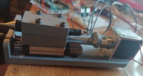
I'm not an mechanical engineer (despite being fascinated by this field) and I need some advice. I'm creating a stippling machine, now it's working but for linear guiding I use linear carriage, which I think is overkill as only thing it does is keeping it from spinning and guiding the needle up and down. Take a look in the photo below.

My question is how can I achieve the same guiding (with spinning prevention) motion cheaper and preferably with less friction? I know that carriage has little to none friction, but I want my contraption to have small weight thus i'm thinking something from nylon without lubricant would have less friction or maybe a better expression less stickiness. But I have no idea how it should look like. I've seen these plastic guides, but they are expensive and im thinking maybe local machinist could make me some dovetail guide-ways or something like that.


Simas
 

Attachments

  • IMG_20201226_122548.jpg
    IMG_20201226_122548.jpg
    85 KB · Views: 263
You're using a solenoid to drive the carriage with the needle, what is the total length of travel in mm? If not very much, investigate "flexures", which could support the carriage while providing essentially "0" friction.

By their nature, you will get some vertical movement (as your picture is oriented) due to the angular movement, but short displacements mean very little change in Z. A longer flexure minimizes this, but can start to compromise other axis control.
 
Thomson linear ball bushings are about the lowest friction you can get off the shelf. About the only lower friction guides are air bearings. They may be too expensive for your application. You will need three bushings and two bars. The open bushings can be adjusted by squeezing the mounting so you can get nearly zero side movement.

Linear Bearings | Thomson | Find a Product

Bill
 
You're using a solenoid to drive the carriage with the needle, what is the total length of travel in mm? If not very much, investigate "flexures", which could support the carriage while providing essentially "0" friction.

By their nature, you will get some vertical movement (as your picture is oriented) due to the angular movement, but short displacements mean very little change in Z. A longer flexure minimizes this, but can start to compromise other axis control.

good idea and of course op can make a flexture without any vertical displacement.
 
good idea and of course op can make a flexture without any vertical displacement.

There's certainly more elaborate flexure designs, but the simplest/cheapest will have some degree of movement. But if you know of an easy to implement version that is vertically stable, please expand on it.
 
There's certainly more elaborate flexure designs, but the simplest/cheapest will have some degree of movement. But if you know of an easy to implement version that is vertically stable, please expand on it.

Why add "easy".....

220px-Roberts_linkage.gif


Roberts Mechanism - Wikipedia
 
Thomson rod and make your carriage from HDPE or Delrin/Acetal. No other bearings needed if drilled properly. Or drill oversize and press some bronze sleeves in.

Or drive a single rod through a pair of "pillow" blocks. Rod attached directly to solenoid.
 
You can also get hardened shafts from DME mold supply. Their prices are reasonable and their ejector pins are very accurate and finished. I have used them a lot for shafts that I wanted to be straight and a good fit in ball bearings.

dme mold - Google Search

Bill
 
it seems to me that the linear guide + carriage in the current design is about the least expensive option considering the low friction requirement, because once you start to use flextures, multiple rods and ball cage bearings etc - you run into manufacturing complexity issues - how to mount those rods parallel, flextures "light" enough to prevent excessive forces needed to move it around and so on

so the current setup is about as cheap as it can get, size of the linear guide could be reduced - save a bit of money there, but anything else will make the end product essentially more expensive without any other benefits

and I'm quite sure that the flexture demonstrated by Mr. Gelbart would end up costing more to make than buying appropriately sized linear guide and carriage

all of the above comes from not knowing what the apparatus is for, so no idea about the necessary positional accuracy which can mean that couple non precision guide rods or even plastic shoe riding on a sheet metal edge might be enough

basically - not enough information in the original post to provide an appropriate solution
 
First of all big thanks for all the ideas, I have never heard of flextures, but they are amazing and I think I'm in a rabbit hole :D

More details. I'm making a stipple machine, but it will burn wood. So for now the price for linear carriage is about 50 Eur (smaller ones are at the same price or more expensive) right now I use mgn12H, because local shop had this on a shelf. The system is quite cheap but I would like to multiply it by 20 so if I could make it half as cheap it will be noticeable.

The accuracy is not that important, but I need repeatability to be around 0,01 mm. The total travel of the contraption should be 1-3mm (more is ok, but not optimal).

The flexture design is really good because of it returns to origin if no force is applied, which is needed in my case (because of fire hazard). So using it I avoid one spring. But I would like to keep the footprint small and I think it will be complicated to get 2mm travel out of 30mm width flexture.
 
and I'm quite sure that the flexture demonstrated by Mr. Gelbart would end up costing more to make than buying appropriately sized linear guide and carriage

Nah, as he said near the end of the video they're free. All you need is a water jet, a spot welder, some scrap steel, and 5 minutes of time. I haven't watched all of his videos, but hopefully one of them shows how he built the machine to slow down time so that a couple hours of labor can be compressed into 5 minutes. You also need one of those university waterjets that come with free electricity, zero cost consumables, and never needs cleaned out.

It did occur to me that if the flexure is just for a prototype the shape shown in that video could probably be 3D printed. In the OP's picture it looks like the base of the contraption is already 3D printed so maybe that's an acceptable solution.
 
You can get cheap linear bearings with hardened track as used "take-offs" from PCB and similar assembly machines. They get sold cheap on eBay sometimes when they are are removed from service for being slightly too worn for their intended application.
 
for just a 1-3mm travel a flexture would certainly make more sense than linear guide, and if you plan to make a run of 20, then I'd order the flat patterns cut by a laser shop, they'll probably have a brake to bend then (design the bends as simple as possible), may even have a spot welder, 3d print a jig to hold everything in place during welding and the price per assembly could be probably brought down to 15-25EUR, depending on how much you can do yourself, that may get you to the 50% reduction in price compared to linear bearing
 
If this for personal use, find a dead optical drive. Many of them have small linear guide mechanisms, and there are lots of examples on youtube where these have been repurposed. A little larger ones can be found in dead inkjet printers or flat bed scanners.


Back
Top