What's new
What's new

Sine Bar Identification and Math Help

  • Thread starter Luke.kerbey
  • Start date
  • Replies 56
  • Views 9,785
L

Luke.kerbey

Guest
sinusoidal sine bar .jpg


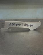
Hi, I have this photo of a sine bar that I found on Facebook a while ago, can anyone share some mathematical knowledge on how I can define this type of curve/radius? once I get the form defined of the shape and the critical parts, I can Wire EDM one out and fudge the scale to make one to my desired size. I'm hoping its not too easy of a problem and that I haven't missed the obvious...
Or even if some of you could argue about how it is best calculated that would be entertaining also.
 
It might be some sort of setting guage, but it's not a sine bar because you cannot define the contact point seperation. A sine bar requires two round dowels seperated at a known distance.
 
It's a cheat! The sine function seems to be built into the end so you get a linear relationship between spacers and angle. It's clever but you lose the advantage of simple geometry and first principles, so it can be checked for accuracy.
 
So how do I replicate it? What type of curve is it?
 
Cad might do, I’ve got access to 2 d CAD and I can work out the rest, is it definitely curve or is it a radius?
 
A device called a French Curve offers a varying curve but i don't know if that curve may be found there.

It is an interesting device. Do check it out to see if it really works.

Oh, you don't own the device. just saw it on face book.
 
Let my clarify,

I can see that the radius above the slip has a 180 degree magnitude and could be called the datum from that radius centre, but I’m assuming that if I give the 90 degree magnitude radius a nominal distance say 100mm or 4 inches I could some how plot the curve from that information? Also that the distance between the 180 and 90 magnitude radius will define the size and centre of the large curve/radius?

I’ve got access to a CAD program called draftsight, (for those who don’t know draftsight is rather versatile and free to download from the internet, also requires little operating power to work) I can trial and error on the form but if someone can explain how the form is defined it may make it a whole lot easier?
 
Boy, you got that right. I suspect that the person who made it DID simply design it point by point with a CAD program, perhaps using 1 degree increments (or less). The thing is, when you rotate the bar by an increment (1°) and raise the left end by an increment ().05"), there are an infinite number of points where the second point on the right end can be located. Each of these points will be at a different horizontal increment from the original, zero angle, point of contact. AND that increment can even change for each point. Thus, that curve on the right could be compressed or stretched by almost any amount and worse yet, it can change shape. I believe that constitutes a double infinity of possible curves. This would make creating an equation more difficult: not impossible, but more difficult. I suspect that cut and try, using CAD would be the easiest way.

All that being said, I don't think the designer did a very good job. 0.05" per degree is not a good number. I would have used 0.06" = 1° which would provide 0.001" = 1 minute. That would have made the math a lot easier for real angles. It also has some limit to the angle that can be made. That should also be recorded on it. I suspect if you go even just a small amount past that limit the calibration of the bar will be way off.

This looks like a nifty experiment. But in the practical world, I think a vernier (or digital) protractor would provide the same or better accuracy and would be a lot easier to use. The real purpose of a sine bar is to allow the construction of PRECISE angles using precise distances. A traditional sine bar does this with the precise spacing of the precisely round pins and the use of precise Jo blocks to establish those exact distances. By using a traditional sine bar you can get angles with accuracies down in the seconds range. This toy will never be that good and there are better, easier ways to set up angles if lower accuracy is all that is needed. As I said, the vernier/digital protractor is one. Another is the use of angle blocks.

I published a method of using angle blocks to set up precise angles of any size (degrees, minutes, and seconds) in the Jan-Feb 2009 issue of Home Shop Machinist. You can check with Village Press for availability of that back issue or reprints. Or you can buy that article here:

Using Angle Gauges for Any Angle - HomemadeTools.net

It also applies the sine principle but in a different manner. And I do discuss the accuracy of the method so you would know where you stand using it.

Edits are in italics.


Gotta think about that! I know how to create it in CAD, piecewise, but a formula will take a bit more brainpower.
 
If you took a 90 deg triangle with 2 sides the same length as the roll c/d and held the vertical side on the center of the moving roll and held the horizontal side horizontal as you raised the moving end wouldn't the end point of the horizontal side generate an involute curve as the c/d changed(providing the base was raised some amount).

With linkage guiding the work piece or the cutter wouldn't you cut the fixed end like the one in the picture,with no math needed?

Cad guys should be able to simulate that.
 
There is an analytical solution but 11.30 pm UK time is way to late for algebraic geometry!

Principle is simple. The length of the line between the two contact points is defined by the sine of the angle. As the angle increases the contact point on the gauge block stack moves round the curve at that end. The contact point on the other ned also moves. The shape of the two curves needs to be such that dividing the height of the gauge block stack by the distance between the contact points gives the sine of the angle with a constant incremental relationship between angle and gauge block stack. In the example that relationship is 50 thou per degree.

If the curve at the gauge block end is a true segment of a circle the longitudinal shift of the contact point for any defined angle can readily be calculated and added to the sine relationship defining the basic shape of the second curve.

The trigonometry section out of Machinery's Handbook has the encessary formulae to develop a functional equation. Real mathematicians won't be impressed but it will work.

When programming it for cutting you need to be very careful where you define the curve from.

Clive
 
I am trying to understand this one. Just what is the "roll c/d"? Is that the Center Distance between the rolls at zero degrees? And what is the "moving roll"? Is that the one on the left in the photo: the one that is assumedly partially round? And are you assuming that the "moving roll" is moving in a circular arc? Because, it would not necessarily do that with the object in the photo.


If you took a 90 deg triangle with 2 sides the same length as the roll c/d and held the vertical side on the center of the moving roll and held the horizontal side horizontal as you raised the moving end wouldn't the end point of the horizontal side generate an involute curve as the c/d changed(providing the base was raised some amount).

With linkage guiding the work piece or the cutter wouldn't you cut the fixed end like the one in the picture,with no math needed?

Cad guys should be able to simulate that.
 
An involute is defined as the locus of a point considered as the end of a taut string being unwound from a given curve in the plane of that curve. What curve would be the basis of this involute?


This is getting above my pay grade but to me if the D snapped roller was the center of a circle of a given diameter that the involute would form the curved pivot. I don’t have the math to back that up though.
 
OK, I have been playing with the geometry in my CAD program and I clearly see a way of generating this curve.

On a vertical mill, use a side cutting cutter that can do the full width of the sine bar in one pass.

1. After all the other features of the bar are finalized, mount it on one side a Rotary Table on the mill, with the left end (the cylindrical resting surface) CENTERED on the axis of the RT. The other side will be facing UP and it will have the end that gets the special curve on the right with that surface toward the front of the mill.

2. Dial in on the top flat of the sine bar to make it parallel to the X (left-right) axis of the mill. Set the angle scale of the RT at ZERO.

3. Touch off your cutter on the "cylindrical resting surface" of the sine bar to get your zero point for the Y axis of the mill. This must be as close as possible.

The following steps would be repeated for each increment to be used. One degree may work or perhaps you would want to go finer: your choice.

4. Move the X axis to the area for the curve and cut a flat all the way across.

5. Rotate the RT by your increment.

6. Move the Y axis of the mill by the desired vertical increment. This must be carefully chosen, depending on the length of the sine bar - more later.

7. Repeat from step # 4 until you reach the largest angle that the sine bar will work for.

That should generate the desired curve. It is mathematically correct for the numbers that you choose to go with. It will NOT work for any arbitrary combination of numbers: some will produce cuts that destroy the previously generated surface. You need to start with a proper set of dimensions and increment to move by.

One thing that I can see that controls the size of the Y move, which is also the constant increment for adding a single degree or whatever increment you choose, is the value of the sine at the maximum angle multiplied by the distance chosen between the contact points at the zero angle. Thus, if you are making a nominal 5" sine bar and want a maximum angle of 45 degrees and for cutting increments of one degree, you would calculate the minimum distance of that increment by:

[5" X sin(45)] - [5" X sin(44)]

or

5" X [sin(45) - sin(44)] = 0.0622"

That seems to be the smallest increment that will work for a 5" / 45° bar. I would conclude that the one in the photo must be around 4" or less.

I still do not know what to name that curve. But this will generate it.
 
For those who may be curious as to how I arrived at the above procedure, here are the drawings I made while contimplating it. First, this is a base drawing showing the sine bar in a 0° position:

attachment.php


I had to guess at the scale so it shows a 5" sine bar; that is 5" between the points of contact at the 0° position. Just as a first guess I put in a circular arc for the mystery curve. I also added two "dots", one at the origin which is the first point of contact and the other at +5, 0 coordinates which is the second point of contact. (I apologize for these dots not showing up in the first drawing above, they seemed to disappear when the drawing was converted to a .bmp file. You can see them in the second drawing below.) The sine bar is at zero degrees.

I have included a "solid" for it to rest on and have labeled the coordinates with conventional X-Y labels and added an "O" designation for the origin.

Then I made a second drawing, well a second layer in the same one. Here I wanted to have a big, easily visible difference so I choose a 20 degree angle for the orientation of the sine bar. You can see how I added that line 20° in the first drawing and it's position and orientation does not change here.

attachment.php


I wanted to keep the left hand point of contact at the same X coordinate so it is still directly above the origin of the X-Y coordinates. After some experiment I found that I had to raise it almost 2" to keep the mystery curve above the top of the surface it is resting on in drawing 1. So I raised it a full 2" (rough guess) and then rotated it by -20 degrees about the center of the left hand circle (X-Y coordinates 0,2). The position of the original 20 degree line is unchanged. I also erased the temporary arc that approximated the mystery curve so it would not confuse the issue. The dot at coordinates 5,0 is also still present and unmoved from the first drawing.

The right hand circle plainly is above the supporting surface. It is also obvious that we need a new point of contact that would be somewhere on the top of that supporting surface. What is not obvious is where on that surface it should be.

While contemplating this situation I imagined doing the same operation for different angles and different elevations at the left side. In each of these different positions the location of the needed support point would be defined by the top of the supporting surface. So I could take the same depiction of the sine bar and rotate/elevate by the various increments and add a short line segment along the top surface of the supporting surface to it. That collection of line segments could be truncated at their intersection points and I would have an approximation of the desired mystery curve.

And then It hit me that the above operations, rotation and elevation, could be easily be performed on a milling machine with a RT. Cut along X axis, rotate by an increment, move along Y axis by an increment, repeat. Bingo! There's your curve.

No proper name. No math beyond adding the increments. And it generates your desired, mystery curve. I would be willing to bet that is how the one in the photo was made.

I do not have a mathematical proof that these line segments will not interfere with each other. Nor do I have any proof that they are an optimal solution for this problem. But I do suspect that they do meet both of these criteria.
 
OK, I have been playing with the geometry in my CAD program and I clearly see a way of generating this curve.

On a vertical mill, use a side cutting cutter that can do the full width of the sine bar in one pass.

1. After all the other features of the bar are finalized, mount it on one side a Rotary Table on the mill, with the left end (the cylindrical resting surface) CENTERED on the axis of the RT. The other side will be facing UP and it will have the end that gets the special curve on the right with that surface toward the front of the mill.

2. Dial in on the top flat of the sine bar to make it parallel to the X (left-right) axis of the mill. Set the angle scale of the RT at ZERO.

3. Touch off your cutter on the "cylindrical resting surface" of the sine bar to get your zero point for the Y axis of the mill. This must be as close as possible.

The following steps would be repeated for each increment to be used. One degree may work or perhaps you would want to go finer: your choice.

4. Move the X axis to the area for the curve and cut a flat all the way across.

5. Rotate the RT by your increment.

6. Move the Y axis of the mill by the desired vertical increment. This must be carefully chosen, depending on the length of the sine bar - more later.

7. Repeat from step # 4 until you reach the largest angle that the sine bar will work for.

That should generate the desired curve. It is mathematically correct for the numbers that you choose to go with. It will NOT work for any arbitrary combination of numbers: some will produce cuts that destroy the previously generated surface. You need to start with a proper set of dimensions and increment to move by.

One thing that I can see that controls the size of the Y move, which is also the constant increment for adding a single degree or whatever increment you choose, is the value of the sine at the maximum angle multiplied by the distance chosen between the contact points at the zero angle. Thus, if you are making a nominal 5" sine bar and want a maximum angle of 45 degrees and for cutting increments of one degree, you would calculate the minimum distance of that increment by:

[5" X sin(45)] - [5" X sin(44)]

or

5" X [sin(45) - sin(44)] = 0.0622"

That seems to be the smallest increment that will work for a 5" / 45° bar. I would conclude that the one in the photo must be around 4" or less.

I still do not know what to name that curve. But this will generate it.

I turned to reddit and was pointed towards Envelope (mathematics) - Wikipedia

Calculus gives me a headache so I will pass on the coursework but this seems to be the mathematical version of what you’re proposing.
 
Yes, precisely! Generating a curve with a network of straight lines. Gear hobbing uses the same idea: each tooth in the hob cuts a straight line. But they add up to an involute curve.

I was really surprised at how easy this one was.


I turned to reddit and was pointed towards Envelope (mathematics) - Wikipedia

Calculus gives me a headache so I will pass on the coursework but this seems to be the mathematical version of what you’re proposing.
 
What I was describing you don't need a rotary table.The sine bar pivots on its RH roll axis,the cutter moves away from from the rh axis the same amount as the cd reduces in the horizontal plane as the lh roll is raised.So the cutter is cutting an increasing radius as the fixed rh roll is rotated.The cutter c/l will always be the same distance from the upward moving roll in the horizontal plane.That will cut a constantly increasing radius from the fixed rh roll(allowed to rotate about its axis ) kinda like an involute?


Back
Top