Planebuilder150
Plastic
- Joined
- Oct 6, 2012
- Location
- Midland Ontario Canada
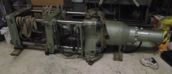
I have a clamping unit from a Nissei 120 ton injection molding machine. I want to stand it up on end, and use it as a press for forming aluminum parts.
I know it will be slow because I will be feeding it with a smaller hydraulic pump that it originally had, but it should have lots of force.
I have built presses with standard cylinders with 2 ports per cylinder, but this one is a bit confusing.
It has a high speed cylinder and a high power cylinder, in one unit. It seems to have 3 pressure lines, ports 1,2 &4 in the pic. Port 3 seems to be a low pressure drain back to the tank?
Any advice on connecting this to a hydraulic power pack would be appreciated.