What's new
What's new

Dimensions question: box & pan brake fingers

CountryBoy19

Stainless
Joined
Aug 14, 2012
Location
Bedford, IN
I have a 24" Diacro box & pan brake I got VERY cheap. It had been damaged and stripped of its fingers. I repaired the damage and I'm now making fingers. Diacro wants $1600 for a set of fingers, complete brakes go for around $1200-1700 used so I can't see spending that much just on fingers. I already had a big chunk of A2 (large enough to make 2 sets) sitting around for several years.

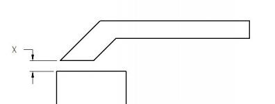
The brake is rated for 16 ga which means it can easily do double that if bending narrow pieces etc. My question is what should the gap labeled "X" on the picture be?
Finger1.jpg

The OE fingers are shaped like the above photo. Obviously the only time the full bottom of the finger is in contact with the workpiece is when the workpiece is X thickness. If that's the case it seems making the fingers like the OE fingers limits my ability to bend a U-shape. Wouldn't it be more effective to make the fingers like the picture below? Is there any reason not to do that?
Finger2.jpg
 
Sometimes the brake is handy for un=bending thin stock and the upper pic would be better for that but more often than not getting odd or myltiple bends close together the lower pic would be better but it sounds like you could have some of each as well as some with a nice radius on the tips
 
Your top leaf should be adjustable as for the amount of clamping of the stock. When the upper leaf is in the open position you should have a fair amount of clearance to allow for passing flanges section as on a box.
 
they make em that way for a reason. my guess is your design will work, but be more likely to break or bend. especially if you overload the brake. Bending short widths of double rated thickness will, eventually, spring the break, warping the top beam, meaning the finished bend will not be a consistent angle.

Brakes have been made for a long time, and they have figured out what works and what doesnt.
I think you will find even 24" of 16 gage is not an easy bend with that little brake.
 
Your top leaf should be adjustable as for the amount of clamping of the stock. When the upper leaf is in the open position you should have a fair amount of clearance to allow for passing flanges section as on a box.

The clamping thickness is adjustable but the rear most point that it pivots about is not so at any material thickness other that X, only the front edge of the finger is clamping the work. I'm just trying to figure out the max thickness a finger should be able to accommodate. If I go by a print I found here the finger would be able to clamp on 5/16" stock which is a bit thick I think. OTOH, if I make that forward edge stick down further I should be able to fit bigger flanges behind the finger. The fingers open up pretty far, over an inch so adding 1/8" to them isn't going to affect the opening in a way that would affect operations.

they make em that way for a reason. my guess is your design will work, but be more likely to break or bend. especially if you overload the brake.
I don't see how that could be. The point of highest stress is right near the top beam. I don't see how removing that extra material under the finger could weaken the finger in the critical area unless I also make the finger thinner which I don't plan to do.

Bending short widths of double rated thickness will, eventually, spring the break, warping the top beam, meaning the finished bend will not be a consistent angle.
This is getting a bit off topic but I think it's valuable to the discussion. Let's say bending a 24" piece of 16 ga takes XYZ force, and bending a 6" piece of 8-ga (twice the thickness but 1/4 the width) exerts the same force. Other than the fact that the finger is seeing increased forces, as long as you aren't exerting that force in the center of the beam I don't think it will exceed the designed load of the beam. That being said, to play it safe it isn't wise to do that as long as it's "equal force" because force concentration is a concern so the total force allowed should be decreased as the force becomes more concentrated. Many brakes actually have a chart that depicts the allowable thickness for various widths. Unfortunately I haven't seen such chart for this one.

I should add that the top beam is very hefty for a 24" brake. It's around 2"x3" solid steel. The whole brake has a listed shipping weight of 325 lbs which is quite hefty for such a little guy.


Back
Top