What's new
What's new

DoAll DBW-15 Wiring Connections

Hoppy

Cast Iron
Joined
Feb 21, 2005
Location
Millington, NJ
I'm trying to bring a DoAll DBW-15 Welder back to life. It's serial #290-745115 and is intended for 220V, single phase operation. There are four wires from the transformer tagged H1, H2, H3, and H4. Can anybody tell me what these get connected to?
 
Send me your email address and I will send you two PDF documents. One is the mechanical set-up and parts break down and the other is a schematic. you will need both.
 
johnoder - Thanks for posting these schematics, but I'm still confused. My transformer has nine leads on the primary side, labeled H1 through H9. The schematics, however, show only four. Leads H5 through H9 are connected to various other components in the welder assembly; leads H1 through H4 are dangling. Any idea where they get connected?
 
I ran into the same issue with my DBW 1A. You will have to remove the face plate for unimpaired access. Then using the schematics you have trace each wire from the xformer and other components and build your own drawing. Unfortunately, my welder is already installed in the saw, which was no small task, so I no longer can see without disassembly.
 
yeah...about 12 years ago I struck forth to get my DBW working. For all I know, it is in perfect shape. But it's not powered, and gaining access to the guts of it is so hard I have never bothered. But I'd like to...

And I wonder just why the thing has keyhole type slots on the front - as if it is meant to be lifted off easily - but then has other bolts on the backside which prevent that from ever happening.
 
These blade welders have been around for many years. The basic design has not changed much over the years. They are very simple, but clever. I see no other way but total disassembly and that is not easy either. What I did is mount a vice on my welding bench to clamp the transformer frame. This allowed me access to the face plate screws. The drive rivets that hold all the data plates to the front plate are very slightly longer than the thickness of the face plate. This allows you to just drive the rivets from the back just enough to grab the rivet with vice-grips. With a slight anticlockwise rotation and a light pull they can be removed and if you are careful reused as well. These rivets are very hard. I bought a small box of them each there are two sizes. They are also expensive for what they are. The wire used is very stiff, which will help you determine where they should connect. Verify with the schematic. These welders are not voltage sensitive at all because the duty cycle is so short. The jaw crush pressure can be adjusted for the heat speed you observe. DoAll also sold these welders as free standing units as well.
 
Removing my welder from the machine was a piece of cake. Remove four screws, tilt the welder out at the top. lift so the stop clears, and it's out!
 
On mine, it is bolted from the front with several screws but also from the back with more screws that are impossible to access front the front and very hard to access from the back.
 
Well....this thread got me motivated to attack mine again and after some deeper looking, I was able to get the welder off. It's sneaky. It's a DBW-8 model, BTW.

Anyway, the fuse looked to be 200 years old and was blown, so I replaced it. But still need to understand how to connect it...I'm thinking it was wired up for three phase 440v but I only have single phase 240v. My 4 incoming terminals were labelled 1,3,4,5. Not sure where #2 went...

I also see the 'Weld' pushbutton is missing. Probably cracked apart as it was probably made out of Bakelite. One thing is for sure...if you were to reach your finger in the hole and push the switch itself, it would work. It would also connect you to the voltage so I'm gonna pass on that.doall welder.jpg
 
After some experimentation, I've reached the point where the DBW-8 is producing a nice looking weld. I don't have the grinder connected so I didn't grind it properly but the weld it self looks good and is strong. I gave the blade a pretty severe bend test and it didn't flinch.

The anneal function might need some attention...it has three positions and I'm not sure #1 is working. On #2, it works 'too good' and heats the blade up very quickly. I think the preference is to get a slow dull red, not a damn fast orange red. I'm not sure but gonna if If I'm feeding the anneal function with 240v when maybe it should be 120v?

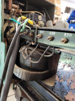
On my transformer, I disconnected the 440v. terminal and fed my 240v instead into the 220v terminal. That seems to have done the trick.DoAll welder ba.jpg
 
The anneal function and blade welder continue to perplex me. In reading the wiring diagrams above, I still can't tell what voltage either is meant to run off, and if that answer differs from diagram to diagram or not.

The issue is...it shows one leg '120' and the other '240'...does that mean the difference is 120, or is it just showing the normal two 120v legs of 240?


Also, my DBW has a transformer that appear to take in 440v and put out a low voltage, high amp feed for the weld. The saw also has a big transformer of its own (not sure what it does?). So in the diagram above, which transformer is being shown? The DBW or the saw's?
 
The DBW does not have room for two transformers physically. I cannot imagine the transformer that steps 440 to 240 being on the welder chassis. We need photos. Further, the control transformer must be fed with 240 as well as the welder.
 
The DBW does not have two transformers; it has one and the saw has one.

The nameplate on the saw shows it was shipped as a 3phase 400v input saw.


1612-3 transformer.jpgDBW transformer.jpg

I also don't understand why a transformer would have a '0' volt tap on it.....
 
Just in the mail is my original DBW-8 manual. And stapled in the front, with one staple, is the electrical diagram. I like this one as it shows the lead labels....still need to understand it though.DoAll DBW-8 elec diagram.jpg


Back
Top