What's new
What's new

Eisele 20" cold saw rebuild questions

M. Moore

Titanium
Joined
Jun 8, 2007
Location
Vancouver Island, B.C. Canada
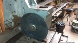
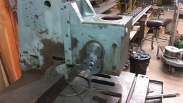
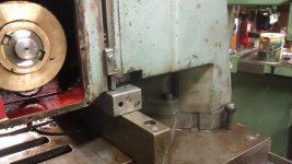
Just in the process of rebuilding the badly neglected and modified machine.
Anyone out there have one of these or a manual for a similar machine?

I think the model is VMS-5. Here is a link to photos of the exact same machine.
Cold Circular Saw EISELE - semiautomatic VMS 5 - PV Saws used machines

I have some basic questions on the air/hydraulic stroke system. Does the ram cylinder have oil above and below the piston? The air line heads into the top cap but there was oil above the piston, the piston is quite different from a normal oil only setup. The rod is also bored out inside and has small inlet grooves at the top (below the piston) to allow oil inside, then a small valve at the bottom of the rod where it connects to the gearbox. The knob can be seen in the photos, it is a small valve and I am wondering about its purpose? Is it to bleed the system? I can provide pics of the piston and rod as it is all apart at the moment.

The unit uses a variable valve on the return oil side to control the down stroke, that is simple to understand. Then the oil flows into the reservoir which has a sight glass to monitor the oil level. The reservoir is also pressurized with air to provide the upstroke with the auto cycle air valves.
I have taken apart the main cylinder but have not done anything yet with the reservoir and wondered if there is just air and oil inside or are they separated somehow?

Right now I am putting new bearings into the gearbox and have some questions about what we found inside. The worm wheel was installed with all of the spring washers facing the same direction and the wheel and gear seemed to be mis-aligned. Why would the worm wheel need a spring type spacer for positioning? Why not have the correct size spacer and tighten it down, done?

I am just waiting on some metric o-rings and then I will be reassembling the gearbox and check the alignment of the worm and wheel, hopefully with the springs correctly installed it will line up on centre.

Thanks for any and all help in getting this old machine up and running again.
I will list all the damage that Bubba did in a future post.

Michael
 
You can't get a manual from the manufacturer? If communicating in a foreign language is a problem, I suggest writing out your inquiry and then using Google Translate to translate it to the desired language. Then send in your inquiry. I found when communicating with Brazilian companies that sending them inquiries in Portuguese worked out a lot better than English. True, the answers came back in Portuguese, but Google Translate did a good enough job that I could understand them fine.

metalmagpie
 
The way you describe it, it sounds like there shouldn't be oil above the piston, but some accommodation would have to be made for normal seepage past the piston. So then it sounds like the small valve would be used to bleed that oil off and allow it to go into the gearbox. Perhaps you'd need to have the blade off so you can run the cylinder full stroke a couple of times to purge that excess oil if you found you ever ran out of stroke because the piston was deadheading against the captive oil.

In some usage patterns, the cylinder may never stroke very far, and you might never notice the captive oil. That's my guess.
 
Metal, I will try the OEM for a manual but I have read that they are less than helpful for their older machine however it is worth a try. A good manual would probably answer some of my questions but probably not any of the rebuild questions.

Hu,
A good guess on the ram question but the top oil inlets are on the oil side of the piston. The rod is bolted through the piston and the small valve on the bottom end just drains oil out the side of the rod, not into the gearbox.
I think that my first guess was correct, it is for bleeding the cylinder as you fill it with oil from the reservoir.
Hit the air switch to start a cycle and the air pressure will fill the cylinder with oil. There is no other obvious way to get oil into the cylinder below the piston.
Thanks for the response it helps me think it all through.
 
I have a smaller one. There should be compressed air to the top of the cylinder ,this gives a positive downward feed. On the up stroke the air above the other cylinder on the side is pressurised ,this pushes the oil through to the up /down cylinder so lifting the blade ,on the down stroke the oil is released from the up/down cylinder via the speed control valve on the operating panel back to the cylinder on the side (there is a piston in there but no rod I think ,it is not just a reservoir).

Regarding the valve ,I think that fine tunes the drop rate ,I have only messed with that once but it did make a difference)

I have had the main spindle out but don't remember spring loading ,it may be to minimise lash which is important on these saws.

I don't think the design has changed much over the years ,mine is 1974.
 
Sable,
I suspected their might be a piston inside the reservoir cylinder as I have not taken it apart yet. I am reluctant to take something apart that is not leaking but I have to take the top off to repair a Bubba fix.
Someone stuck a regular bolt into a pipe thread and somehow made it seal, it is an ugly bit of work.
I definitely think this machine is from the 70’s and the gearbox has been apart several times as far as I can tell from the damage to the lock nuts.

The worm wheel is not in great shape but hopefully it will hold up for a while. There may not have been much lash when it was new but there is some lash now and there is no way to eliminate or adjust it out that I can see, the worm wheel is not adjustable nor is the gear shaft and I can’t see what any adjustment would do in any case as the worm wheel teeth are worn.

It probably doesn’t help that it was running backwards for some time given the wear on the wrong side of the worm wheel teeth. Without the manual or internet many would assume that the blade should rotate towards the column, not away as it should be done.

Sable, do you have a manual for your machine? Have you ever contacted Eisele directly?

Michael
 
Michael ,I don't have a manual and I have not contacted Eisele.

You are correct about the rotation ,what I don't get is how they avoided the bolt undoing that holds the blade on ,I know there are dowels but even so.

One thing I have thought of since my previous post, I had the top off both cylinders and cleaned up the bores as there was quite a bit of surface rust ,it was causing them to stick which tends to result in a broken blade.

When I first got mine I couldn't get on with it at all ,the main issue was trying to use a blade with too many teeth to cut large solid bar ,the head would stick slightly then drop all of a sudden and grab ,I was breaking dowels all the time and operating this thing was a butt clenching operation to say the least. My tool man recommended a more suitable blade and now I love it ,it does need an overhaul really but I don't use it a lot so it does me fine.
 
Sable,

The bolt holding the blade is a right hand thread, if the blade slips the bolt will tighten up, assuming the dowels are missing.
I would like to replace the dowels on the clamp washer as they are quite beat up, any suggestions for a material choice?

The bore on the main cylinder is in quite good condition all things considered, no rust inside except for a ring near the bottom of the oil chamber.
I have yet to check the reservoir cylinder as I was busy today re-assembling the gearbox and testing the whole thing, it works!

I put the 16" blade on there to show the size, she is a big girl. A 20" blade is going to run about $700.

Two of the photo's are as found and three are from today reassembling and testing. I hooked up a switch and put power to the motor.
Got the rotation right on the first try! Can't wait to cut some metal!

Now that the gearbox is done I will put my efforts into the hydraulic system overhaul. The first step is finding some suitable fittings and air line to replace what is there now. I assumed that the fittings were metric but I haven't had a chance to actually measure them yet, is it possible that germany used BSPP threads way back in the 70's? If so it will be a lot easier to find some adapters to JIC or SAE whichever I choose as that wimpy clear (not anymore) air line is easily kinked and damaged. I would like to keep all the air switches as they appear to be working fine. The system did cycle when I put air to it but the previous owner said it was prone to dropping and there was a "vacuum" leak somewhere. They never used the saw, it just sat in the shop for a few years and now it is mine.

One or more of the previous previous owners was a real Bubba and among other things they cut the vice somewhat in half and threw away the bigger part. Then they cut and welded the screw so it could not be removed without cutting it apart, etc etc. I think I can make a new gib for it and have about 4" of travel and use spacer blocks bolted on to give me a full clamping range as well as get the air clamp working again.

Michael
 

Attachments

  • coldsaw2.jpg
    coldsaw2.jpg
    96.7 KB · Views: 335
  • coldsaw1.jpg
    coldsaw1.jpg
    98.1 KB · Views: 197
  • coldsaw3.jpg
    coldsaw3.jpg
    93.4 KB · Views: 271
  • coldsaw4.jpg
    coldsaw4.jpg
    96.6 KB · Views: 262
  • coldsaw5.jpg
    coldsaw5.jpg
    97.2 KB · Views: 208
Two more photos for the record, disassembly time.

The as cast gear teeth are a bit of fun, it turns very well now that it is all clean again.
A couple of hours with a 3000 psi pressure washer fed with hot water did the trick, messy but good result.

Why is every part of everything I work on so darn heavy????

More work from Bubba, you can see the corner of the casting missing in the first photo right above the 2x3" block.
They CUT OFF the end of the hardened way and broke out the casting, for what reason???? I can't figure that one out.

40 plus years of service and I can't see any visible wear on the ways or the adjustable gibs which are usually max'ed out by the time I get the machine. LOL.
 

Attachments

  • coldsaw6.jpg
    coldsaw6.jpg
    93.7 KB · Views: 215
  • coldsaw7.jpg
    coldsaw7.jpg
    97.3 KB · Views: 270
I think the fittings will be metric. I make my dowels from silver steel and turn them to leave a small head ,this stops them going too far into the spindle flange. I have had problems with mine in that the dowel holes in the flange are damaged so the remains of a broken dowel can get stuck .Not so much of a problem now I don't break them very often.

Yours is a much bigger machine ,mine is only 14" blade and the slides are two round bars.
 
Sable,
I am not familiar with Silver steel, do you have any numbers to go with that type?
It finally took the reservoir apart and as I suspected there is no piston inside, just air and oil.
It has a special sintered filter at the top with a passage for the oil when you fill or replenish.
Anything special about the oil for an air/oil system? I was just going to use a light hydraulic oil.
I read something about special oil for the gearbox but I can't see any real need for it, I used Turbine 32 as it was the right oil type for my Dean Smith Grace lathe headstock so it should be fine for a German gearbox!
I ordered some DIN fittings and the 8 mm tubing to repair all the air lines so that should be here in a few weeks, not much of that kind of thing is available in this part of the world.

Michael
 
Michael,

Silver steel is the high carbon steel rod that you buy in 13" rods ,centreless ground on the outsde, used to be called cast steel not sure what you call it. It was just what I had that was the right diameter and harder than mild ,I did not harden it.

My memory must have failed me, or perhaps I imagined that there was a piston in the reservoir. I don't think mine has the filter but I know it has a badly chewed up red filler plug. I just put 32 hydraulic oil in mine.I think I put gear oil in the gearbox but that is probably not correct because of the phosphor bronze worm wheel. I thought the loads in that gearbox were quite high with all that reduction but I guess it is only a pretty small motor at the end of the day.
 
Sable,
Does your machine have an air operated vice?
Bubba attacked the vise on this one and the air clamp is missing the adapter plate to bolt it to the vice.
The strange part is that the holes in the end of the vise are tapped and the holes in the air clamp are tapped, different layout of hole spacing...
The only solution that I can come up with is to use two plates and then bolt the plates together. I can’t see any other way to make it happen as the bolt holes are covered on each part if you put the parts together.
I tried to look at photos of Eisele vises online and it looks like one plate attaches the air clamp but I have not found a real clear close up photo of the area.

I actually got the gearbox filled with oil, and the air system temporarily connected and then I filled the air system with oil and put some air pressure to it and voila, it goes up and down. The main cylinder is pitted from rust and needs to be replaced, the piston looks ok but probably best to replace it as well. The air is bypassing and causing some uneven travel or “bounce” which is a real problem with this setup. At some speed rates it travels smoothly but when you slow it down it starts to stick/slip all the way down.

Any recommendations on a company that sells air/hydraulic parts anyone? I can modify any parts to fit the end caps of what I have and get it up and running like new again if I can find the parts. OEM does not support this model from about 1974/5 anymore.

Michael
 
Forgot to ask if chrome plating of the cylinder would be able to fix the pitting from the rust?
Making it slightly undersize would probably be fine for the piston. The piston looks like two axle seals back to back with a center disc of steel to attach the rod, not your normal hydraulic piston.
 
I do have the air vices. Mine is a smaller machine than yours so the vice may be different ,I actually have two vices ,one for either side of the cut.

It is vital that the feed action is smooth as I am sure you realise.

I will have a look at the vices to see if they are similar.
 
Sable,
I ended up using a two plate system but I am still curious how the original vices were done.

I also need a favour with the air vice connections, nothing is remaining on this machine and I need to know how the vice was connected into the air system. I think that there is another valve that actuates at the top of the return stroke which releases the vice, not sure how it clamps.
Any help or pictures with that setup would be much appreciated as air control systems are definitely not my specialty.

I have now replaced the cylinder with a new one that I made and I just re-used the old piston which looked visually to be in good condition.
It was a long 24 hours to wait for the gasket goo to cure and I fired it up today. After a bit of a mixup with the air line connections it now works nearly perfectly! Nice and smooth feed as it should.
I did do some test cuts but don't have the coolant system done so it was just a few cuts and it works very well.

So, $500 cost, $500 in parts so far, total spend $1200 + some time = $40,000 replacement cost!

I will post some more pics later.

Michael
 
HI Did you ever get a manual?
as i recently got a vms 440 and want to restore the one i have as well.
sadly mine is missing a few pieces


Back
Top