What's new
What's new

Enco/Gamet Boring Facing Head Disassembly?

dalmatiangirl61

Diamond
Joined
Jan 31, 2011
Location
BFE Nevada/San Marcos Tx
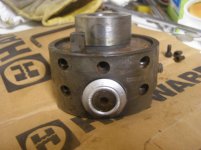
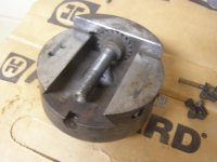
I picked up this boring head about 5 years ago, it was rusty on 1 side at the time, and soaking wet as it was a rainy day, gave $1 for it. I sprayed it down with oil that day, it been in storage since. Dropped it in a bucket of evap for a few hours yesterday, spent about a half hour cleaning and trying to disassemble before I decided I needed more info before I broke it.

Came onto PM thinking I could find more info and I did, just not how to take it apart, seems most just end with "I got it". I think this is correct manual Enco Boring Head.pdf - Box

I initially started with trying to remove top ring, there are 2 setscrews, 1 turns but now know its #9? the autofeed cam, the round hole is #2 is the fixed cam, there is 1 more allen head screw? it is not moving.

So how do I get this thing apart? Warnings appreciated!
 

Attachments

  • egbh 1.jpg
    egbh 1.jpg
    97.3 KB · Views: 253
  • egbh 2.jpg
    egbh 2.jpg
    96.1 KB · Views: 184
  • egbh 3.jpg
    egbh 3.jpg
    97.1 KB · Views: 194
I have the same boring head, sans the Enco logo. I scanned a exploded view of the boring head but it's too large and PM will not allow to post it. If you think you may want to take a look at it, email me and I'll send it to you as a PDF. That seems to be the easiest way to do it, but I'm not a tech guru so I'm not sure.


Stuart
 
There is an exploded view on the link for manual, but that does not really help me. Once I can figure out where to start I might figure the rest out, just don't want to do something stupid.

I initially thought it was just a boring head and it would just be clean the dovetails. After evapo dunk and things started looking like there were other features I came here looking for more info, looks like some slightly complicated internals. Rinsed and soaked in water but evap spooge was still leaking out while fooling with it, would like to clean that stuff out.
 
Wish I had your R-8 shank there. Mine came with a no. 5MT shank. Plan on making a R-8 shank for it someday. As for taking the head apart, I haven't tried, yet. Ken
 
Wish I had your R-8 shank there. Mine came with a no. 5MT shank. Plan on making a R-8 shank for it someday. As for taking the head apart, I haven't tried, yet. Ken

What I need is a #9 B&S shank, was already thinking I might have to make one, hmm, need to look at 5mt dimensions and see if that could be turned to 9bs.
 
First, unscrew the shank. Standard right hand thread. That holds the ratcheting mechanism in place. There is a set screw to lock the shank, and it appears you have it backed out.

The hex sockets in the top ring are not screws. They are cams that allow you to retract the dogs that cause the head to feed out. One is fixed on, and two others can be set to cause feed or not. There is a line on the socket to tell you whether it is on or off.
 
Yeah, the 5MT shank on mine is harden. I assume it's case harden. Strangely, for this to be almost all metric, the thread used on the shank of this head is a .938-12 pitch thread. Did make a drawing of the thread and the part that registers with the head. It's here somewhere on my computer. Ken
 
Ok progress, step 1 using dial on side extend till travel stops, the screw being pointed at in first pic below must be removed as it is a stop. Step 2, to unscrew shank, remove setscrew with brass slug locking shank threads, with a machine that it fits in it is easier to hold, without you have to use alternate methods, what worked for me was a spanner on body with a pipe cheater, then a pipe wrench on shank, using larger pipe wrench as a hammer for a good sharp blow. Step 1 & 2 are interchangeable.

4GSR, only a slight nick on shank, sorry!
 

Attachments

  • egbh 4.jpg
    egbh 4.jpg
    96.1 KB · Views: 285
  • egbh 5.jpg
    egbh 5.jpg
    95.4 KB · Views: 195
  • egbh 6.jpg
    egbh 6.jpg
    96.3 KB · Views: 207
Pure speculation here.

Graham Meek had a design for a boring and facing head that had features that sound similar. It's possible he's been inside one and spun out his design from there. The mechanism utilizes a star wheel with a cam that can be turned to trip it on each revolution or not. Further, there are two on opposite sides meaning you can get two feed speeds by engaging both. Plus, there's another star wheel on the opposite end of the shaft such that the cams can offer opposite feed.

If it's similar enough, the plate holding the dial also covers the gear train from the star wheel shaft to the feed screw.

Does this sound similar enough to merit looking at his design? If he's sort of copied the ideas he'd have implemented similar parts.

<edit> Ah well, way ahead of me already.
 
With the shank removed the knurled ring should lift off. If not, its stuck. The knurled ring should spin freely.
 
Ah, yes. Manana. So many of us gringos get it wrong, thinking it actually means tomorrow. In reality its much simpler. It just means "not today".
 
It is snowing today, so manana is finally here.

First 2 pics below is the top ring removed, not sure if cams can be removed for cleaning (they went in somehow), need to investigate further. 3rd pic is the 5 allen bolts that need to be removed, I tried manana but they were stuck so left them to soak with PB for another 2 mananas:).

Fourth pic, this is where I'm stuck, I think the section with the screw should separate from main body, I think exploded diagram shows dowels pins, I have hammered (lead) and tried prying thru the square hole to separate these pieces to no avail. So I'm at "stop before you break it", am I missing a disassembly step, or should I hammer harder?
 

Attachments

  • egbh 7.jpg
    egbh 7.jpg
    94.5 KB · Views: 129
  • egbh 8.jpg
    egbh 8.jpg
    96.4 KB · Views: 122
  • egbh 9.jpg
    egbh 9.jpg
    84.9 KB · Views: 163
  • egbh 10.jpg
    egbh 10.jpg
    82.1 KB · Views: 221
I looked at my drawing and I see the dowel pins you refer to. I see no other items fastening those two pieces together so my thought would be a factory tight fit plus years of fugus are holding them together. There is a wave washer/friction spring in that screw assembly so any heat application may kill it. I would continue to soak in something, then, holding your mouth just right, start tapping with a hammer. Use a brass punch and hammer down near the gear so you get more of a equal 'push' on the tight fitting dowel pins.

You could also screw in some sacrificial long SHCS, support the outer piece on the edges, and hammer on the SHCS..that way you could distribute your banging evenly, and again, not put the dowels in a bind.

Stuart
 
Okay, yaw got my curiosity up, went out to the shop and took my boring head apart. Took about 20 minutes to get most of it apart. Yeah, the piece in your picture 4 took a little persuasion to get it off. If you have a brass drift, place it down in the dovetail next to the gear as Stuart mentioned. Gentle tapping with a 8 oz ball peen hammer, moving the brass drift from side to side, will drive the end piece off. I did not mess with the screw assy. The piece/ring with the three cam looking levers mounted, don't attempt to take it apart. I did one and there is a very small c-ring that holds the shaft in place. I don't know how I'm going to get that c-ring back on the shaft. There's very little room to work in that piece. I hope this helps. I was very surprised how easy it was to dismantle this boring head. Mind is dirty, got an excuse now to clean it. Ken20201108_201321_resized.jpg20201108_201402_resized.jpg20201108_201348_resized.jpg
 
Okay, yaw got my curiosity up, went out to the shop and took my boring head apart. Took about 20 minutes to get most of it apart. Yeah, the piece in your picture 4 took a little persuasion to get it off. If you have a brass drift, place it down in the dovetail next to the gear as Stuart mentioned. Gentle tapping with a 8 oz ball peen hammer, moving the brass drift from side to side, will drive the end piece off. I did not mess with the screw assy. The piece/ring with the three cam looking levers mounted, don't attempt to take it apart. I did one and there is a very small c-ring that holds the shaft in place. I don't know how I'm going to get that c-ring back on the shaft. There's very little room to work in that piece. I hope this helps. I was very surprised how easy it was to dismantle this boring head. Mind is dirty, got an excuse now to clean it. KenView attachment 304155View attachment 304156View attachment 304157

Yours looks MUCH cleaner than mine! Got the piece with the screw off last night, punch and some hammering did the trick. I was studying the cam ring a few minutes ago, the round hole is a fixed cam, setscrew #1 moves(rotates) and has a cam that can be engaged/disengaged, setscrew #2 looks like it is a cam also, currently disengaged, but does not turn, soaking in penetrant now. Is yours the same?

Edit: Re-read manual, it appears this has 3 feed speeds (COOL!) and the second cam should actuate, its back in for another soak bath to loosen.
 
Last edited:
...........................................................Is yours the same?

Edit: Re-read manual, it appears this has 3 feed speeds (COOL!) and the second cam should actuate, its back in for another soak bath to loosen.

Yes, mine is identical to yours, except for the rust....:o

On the operation of the cams, when all three are up or extended, that give you your coarser feed per revolution. If just one is extended, that will give you your finer feed per revolution. And with just two of the cams extended, will give you the medium feed per revolution. And I would have to go dig up the paper work to tell you what those feed increments are.

If you decide to part with that R-8 shank, let me know, I'll be glad to buy it from you for a reasonable price.:)

Ken


Back
Top