What's new
What's new

Famco Arbor Press Disassembly

kjones95206

Plastic
Joined
Jul 18, 2017
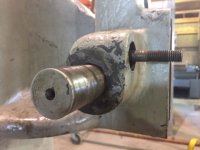
I have a Famco 6C (15 ton) arbor press that I am disassembling for cleaning and painting. I'm not sure how the cross shaft gears are removed. Are the two spur gears one cluster gear or two separate gears? Do I pull the right gear off of the shaft from left to right? How is the center gear removed?
I am reluctant to start pulling with a puller without a better idea of how it was assembled.
The second middle photograph is taken from the right side of the machine and the photograph on the far right is taken from the left side of the machine.
Thanks for your advice.

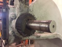
IMG_0718.JPGIMG_0719.JPGIMG_0720.JPG
 
There is a pratt and whitney key under the ratchet gear, so don't thrust the shaft from right to left of image 1. if possible get a pair of wood chisels hammered towards each other and pull the ratchet off if a gear puller doesn't fit the gap. There might be a surprise like a circle of screws behind the ratchet. Try looking from the bottom up and the top down there might be a set screw in a groove in a shaft preventing the shaft from moving left or right.
 
Mine just pushed out to the right... but take care with tiny burrs on the internal gears - they need to be stoned off or may stop it passing though the bore.
 
Thanks for the help. I was able to pull the ratchet gear off, but only after applying some heat (it was really tight on the shaft!). The tip on removing the burrs from the spline gear was important because the shaft would not have come out of the housing with those burrs... a really tight fit also.
I will get it cleaned, painted, and reassembled.
Thanks again.
IMG_0733b.jpgIMG_0731.JPG
 
I want to buy Famco Arbor Press , But for who buy this arbor press can you share your experience with it.

Does it deserve buying?
 
Kjones,
I am in the same boat, same model.
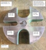
Thank you for the post! I am wondering if anyone has dimensions on the daisy wheel (press plate/platen), or a pattern? Mine was missing that part. I have some thick 1 1-2" stock I’m going to have burned or jetted out.
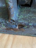
Also, mine has a couple of chunks missing in the casting. Looks like someone tried to weld it w/nickel rod. I am wondering what you guys think... should I leave them alone or try to silicon braze them up? The casting itself is about an 1-1/8" or so.
The damage is deep, maybe 1/2". I know it would take a rosebud and lots of time, with a weld blanket cool down. I am more concerned about the damage in the slots the table rides up and down in. I don't want to make it worse.
I posted in an older thread on this topic too, sorry.
Press 1.jpg
 

Attachments

  • Press 1.jpg
    Press 1.jpg
    97.4 KB · Views: 68
Last edited:
If your press were mine, I would fill the voids in the casting with body filler, sand, and paint.
That's what I did with mine. These castings are beasts and trying to weld them to fill the voids is unnecessary; IMO

Famco 6C.JPG
 
Thanks Kjones,
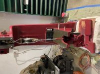
That is my conclusion as well. In the meantime, the missing daisy wheel is the least of my problems. Buyer beware. The compound block is missing, and some one in the past modified the pinion shaft, and added an archaic balancing arm for an R type model. In talking to Famco direct, they used to use the same forging for BOTH the 6R and 6C. Mine appears mickey moused with a shop made shaft? So, I can spend about 2K to get it back to stock, or try to make a working 6R out of it. Balancing arm won't stay up and the handwheel doesn't retract ram.
Now, I am just trying to get shaft out to right side as operator faces machine, but this handwheel is stuck like nothing I've ever encountered. There are no additional set screws except the one I removed. I think someone hammered/mushroomed the shaft. Bearing splitter, heat and a large puller won't remove it. I'll post pics as soon as I figure out how to get rid of Apple's brilliant idea to convert all photos to unsupported .HEIC format.
 
So an update on my Famco 6C... I decided buy the OEM parts to make it right($$$). Ready for reassembly except for strange bore diameters in the casting, new compound and balancing arm . The compound and balancing arm ride on two pins, depending leverage desired. Factory sent new parts with bores varying between 1.114" and 1.118". Bores in main casting similar, more or less. Seems like a lot of play for a 1-1/16" nominal shaft (weird nominal size to begin with). Maybe they smoked a fatty at lunch and forgot to ream them, lol.
Some notes: taking off the handwheel was a bear. Had to gently sand off the mushroom on hand wheel end after stoning didn't work. The previous owner tried to use some 4R parts on this machine. While similar diameters, shaft lengths all wrong.
Anyway, thank you to Kjones for the advice,I took it down to bare iron, filled the nasty divots with body filler and called it good.
I now have a 4R shaft and balancing arm for sale, should anyone need one. Famco wants bank for these parts . I also replaced the table gear, two busted teeth. This could be braised and fixed if one had the right gear cutter. If someone needs the gear I'll give it to you. The main shaft is still good, no damage except where I had to tune it up to remove handwheel. Could be built-up and turned, or used as is.
2F851B1C-D0A4-4242-8E0E-1B24840C48BA.jpg56FC3D09-B1AE-4AAA-AC2F-6663A441050D.jpg
 

Attachments

  • 18452B07-2C51-4AD3-AC96-E39DED42FA10.jpg
    18452B07-2C51-4AD3-AC96-E39DED42FA10.jpg
    19.8 KB · Views: 35
Last edited:


Back
Top