What's new
What's new

Fixturing an Imperfect Cylinder

opscimc

Stainless
Joined
Jan 24, 2012
Location
Southwest
I have to TIG weld a significant missing chuck of aluminum on the base of the cylinder of a 70-year old motorcycle, clean up the bore, then press the sleeve in. The welding will distort at least one end of the aluminum cylinder resulting in it being egg-shaped and hourglass-shaped to some extent. However, if I am able to mount it in the lathe afterwards with its undulating-and-imperfect bore being, on average, precisely parallel with the axis of the lathe it will require the minimum amount of metal to be removed. The current interference fit is 0.002" so there isn't much room for material removal (although an oversize sleeve may be available).

Clearly, if the bore were a perfect cylindrical surface I could easily adjust it to within a tenth in a 4-jaw chuck. But, leaving aside issues of stress relieving, whether there might be too much distortion for a subsequent press fit of the sleeve, trying to find a replacement cylinder instead, etc., my question is simply how best to "index" an imperfect internal cylindrical surface when mounting the repaired piece in the lathe.

Assume that all the usual lathe attachments are available (chucks, live and dead centers, faceplates, etc.), and that measurements will be made manually. The bore and length of the cylinder are approximately 3⅜" and 6", respectively. Or, after removing the bulk of the TIG-added material in the lathe, would it be better (i.e. remove less material) to restore the internal surface using my Sunnen hone rather than my lathe? I have the necessary AN-600 Honing Head.
 
As I understand your problem, you have a job better done in a Bridgeport style mill.

You can mount the cylinder on the table in approximately the correct orientation. Overly secure clamping is not necessary, as you are not rotating the the part at some rpm. You can then tram the head in two directions to match the angular orientation of the barrel, and move the table and saddle for location. You can then use a much higher cutting speed on the usually somewhat gummy weld area.

If you are not familiar with working in this manner, anytime you move your knee you have to pick up the location again.
 
You can buy or have made cheaply cast sleeves in any conceivable size you want. You just spec what you need.

I'd lean towards having the bore in the correct planes and using a sleeve that accommodates that.
 
a job better done in a Bridgeport style mill.
I have a mill, and gravity makes mounting the cylinder on the table easier than mounting in a lathe, but the fundamental question remains the same.

Because "cylinder" is used in two ways, instead I'll refer to the Al motorcycle part with fins on it as the '************'. Leaving aside a few important "details," if I made a solid cylinder that was a slip fit in the ************, and that had accurate countersink holes at both ends, I could hold one end in a projection on the table (set to 0,0 on the DRO) while holding the other end with a projection mounted in the spindle of the mill. If I then were able to clamp the ************ to the table without tilting it as I did so, that would ensure the axis of the ************ was as parallel to the axis of the mill as one could hope irrespective of undulations on the inner surface of the ************. Clearly, "details" include how to actually manage to clamp the ************ tightly without tilting it so the cylinder could then be removed. Basically, the same process could be used in a lathe.
 
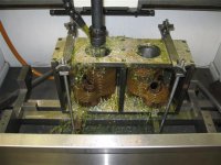
I sleeve a lot of old blind bike cylinders. I've done Harley, Ace, Excelsior, Thor and others on this fixture. This shows it in my hone with a pair of JD jugs but the same fixture bolts to the table of my CNC mill for sleeving/boring. Does your cylinder have the same flange type mount as these? That's why I built the fixture, the flange of the cylinder bolts to the bottom of the top plate which is parallel to the table, so it automatically squares the bore to the machine, no other dialing required. Surprisingly those old cylinders are always dead square to the flange.

IMG_1497 (Small).JPG
 
...this fixture.
That's a nice setup. I may have to do something similar but the welding will be done at the mounting flange end so that's where the potential of distortion is greatest so there's no guarantee the bore will be square to the mounting flange afterwards even if it might be perfectly square before.
 
Indicate and if possible, fixture from the undamaged end. Then make the new work match the old. This will likely take longer but the results tend to be worth it.
 
Trying to "average out" the cylinder distortion by mounting it on a cylindrical mandrel, as you described, will not really guarantee that you are taking the best alignment, for minimal material removal.

The mandrel only knows about the "minimum" diameter spots in the bore, and knows nothing about how much the places where it doesn't touch are out of whack.
 
Indicate and if possible, fixture from the undamaged end.
That might help to some extent but I'll have to see. The cylinder is currently immersed in a degreasing bath where I'll leave it for another week, but then I'll test various mounting and registration suggestions before I do any welding.
As far as installing the sleeve, I never press, I always use nitrogen.
I wrote "press" as a general term, but liquid nitrogen is my friend as well.
 
I have a mill, and gravity makes mounting the cylinder on the table easier than mounting in a lathe, but the fundamental question remains the same.

If you mount it on a plug, you are working with the largest possible cylinder. If the entry end is tight or if the hole is lobed, it may do a very poor job of representing a best fit axis.

On a vertical mill I find it easier to inspect the bore geometry after the axis have been adjusted for best fit. With the vertical mill, you can tram both sides of the diameter for a given axis, adjusting to even out taper. After you think you have the axis angles correct, you can inspect for the largest possible diameter. Then you have to make the choice whether or not you will remove enough material to clean up that spot, or what size bald spot is acceptable. But the key, to me, is knowing exactly how much material will be removed, and where.
 
I'll follow up on the milling machine suggestions once I remove it from the degreaser and before I do any welding. I'll see what issues there are to deal with when mounting it that way. Thanks for those suggestions.
 
" Surprisingly those old cylinders are always dead square to the flange."

People in magazines love to rag on old-time machining, especially production line work. They are confident that in the old days, before CNC and millenials came along, no one could machine anything. In my experience, whenever I measure stuff from back then, it's pretty damn good.

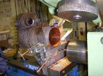
We did a favor and cleaned up the mounting flanges on an old HD jug, similar to the ones shown in the photo, fixured for boring. The castings were
simply amazing. I have no idea how they managed to sand cast such intricate features. These were I over E jugs BTW. I doubt these could be
replicated from scratch these days.
 
To reduce wattage from welding could a plug be made to support shape?

We understand that warm metal that changes shape is less solid so to speak and may move differently if restrained, lengthwise maybe, but upon cooling it may settle back when cooled.

Unsupported it warps then warps different as cools.

Even a cut plug of wood would restrain movement while not removing heat.


Sent from my SAMSUNG-SM-G930A using Tapatalk
 
We did a favor and cleaned up the mounting flanges on an old HD jug, similar to the ones shown in the photo, fixured for boring. The castings were
simply amazing. I have no idea how they managed to sand cast such intricate features. These were I over E jugs BTW. I doubt these could be
replicated from scratch these days.

Actually Jim, those IOE (JD) cylinders are duplicated. They became rare and expensive enough that someone is casting them again. I might see some soon, a customer has a set he wants bored.
 
Actually Jim, those IOE (JD) cylinders are duplicated. They became rare and expensive enough that someone is casting them again. I might see some soon, a customer has a set he wants bored.

In our case an owner had welded up the bottom flange because the holes had been buggered. We had to machine
out new holes where the welds were very hard. This is an original jug:
 

Attachments

  • jug_fix_3.jpg
    jug_fix_3.jpg
    96.5 KB · Views: 73
  • jug_fix_4.jpg
    jug_fix_4.jpg
    94.9 KB · Views: 78


Back
Top