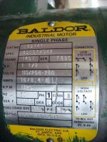
Baldor motor diagram for your motor does not mention lead 9, but for low voltage
leads 1+3 and 2+4 are always connected together and leads 5 and 8, the start
windings, are used to reverse the motor. Drum switches have 6 positions, labeled
1 thro 6 (natch) and for your motor positions 2 and 6 are connected to the 115Vac
line. Then 1+3 motor wires are connected to position 2 on the switch and motor
wires 2+4 connect to position 5 on the drum. Position 5 and 3 are shorted together
on the drum. motor wire 8 goes to position 1 on the switch and motor wire 5 goes
to position 4 on the switch. If the motor goes the 'wrong' way when the switch is
thrown just reverse motor leads 5 and 8 on the switch.
Can't find the simple diagram but page 15 at this pdf has the drum diagram:
http://ecatalog.squared.com/pubs/Machine Control/0140CT9201.pdf
and your motor is at page 9 here:
http://attachments.temcoindustrialpower.com/product_info/Baldor-L3514T.pdf
On the drum switch pdf, fig 1 is the switch configuration, lever to L, centered and lever to R, and fig 3 is your motor connex to the switch.
Here is one of many posts on this forum on the same question with a few diagrams:
http://www.practicalmachinist.com/vb/south-bend-lathes/9a-motor-drum-switch-wiring-help-205264/