What's new
What's new

Help with DoAll bandsaw model ML problems

ff2018

Plastic
Joined
Sep 21, 2019
Purchased a DoAll model ML bandsaw at auction (photo below). Per the serial number I think it was made in 1950 (first two digits of the SN).

6 (2).jpg

The plate on the machine says it needs 440V 3-phase 60hz power (the standard back in 1950) but we've wired it to 480V 3-phase 60hz (photo below).

2 (2).jpg

The problem is when we turn the saw on it'll run for 5-10 seconds before tripping the B2.10 square D thermal unit inside the on/off switch assembly and shutting off. I've replaced the thermal units but the saw still shuts off after a few seconds (and it smokes from the thermal unit). Photo below of what I'm talking about.
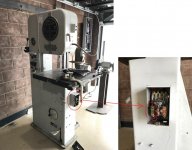
thermal_unit.jpg

Does anyone have any ideas on what's going on with this thing? This saw is brand new to us and I'm not an electrician so any suggestions would be super appreciated (even if they are obvious ones like check speed settings).

Thank you!
 
Does anyone have any ideas on what's going on with this thing?

Has the blade welder - all of which required two hots of 220 volts. This was done with a transformer on board. Might want to see WHERE your 480 was hooked up to

Probably smart to ALSO see if this thing has been repowered / rewired for maybe single phase - in other words, don't be so trusting of 70 year old tags specifying power required. A look at the data tag on the motor may be an eye opener
 
I'll take some additional photos but the blade welder seems to work (haven't tested the actual welder but the grinding wheel turns on when we flip the switch).
 
well, you are giving it 10% over the voltage that was intended for it 70 years ago. might be a problem, but seems like it wouldn't really blow things under a no load condition.

have you checked the motor plate to see if the motor was replaced with a 208 or 240 unit? (or single phase as John said, just re-read that, he beat me to it!)
has the motor been rewired internally for the lower voltage?
try testing/disconnecting the transformer John mentioned, if that, or the blade welder is damaged/faulty it could be the problem.
check the wires for the lamp and auxiliary receptacle for damage/short.
there is probably another transformer to step down to 115v for the lamps, check that too.
put a meeter on your input to confirm the voltage (that is not an over voltage condition)
 
Photo of the motor: 20.jpg

Unfortunately I'm not an electrician...if I pull the electrical covers over the motor how would I know if it's been rewired for a lower voltage? This seems like the first thing to check since from what I've been able to find online it looks like a lot of people rewire these units for lower voltage.

Disconnecting the other transformers is a great idea too so if the motor is indeed wired for 440 we can start to isolate where the problem may be.
 

he wes talking about INTERNAL connections, lots of things my have been done to the electrics on an old machine, seen some truly unbelievable stuff! being that you are powering 70 year old machine with 480, you are getting into dangerous territory. the possibility of a fatal shock is much higher, and if you have not tested/inspected everything, or had a competent professional go through the machine (from your questions ill take it you are not that guy), that would be a really smart thing to do.
 
he wes talking about INTERNAL connections, lots of things my have been done to the electrics on an old machine, seen some truly unbelievable stuff! being that you are powering 70 year old machine with 480, you are getting into dangerous territory. the possibility of a fatal shock is much higher, and if you have not tested/inspected everything, or had a competent professional go through the machine (from your questions ill take it you are not that guy), that would be a really smart thing to do.

Gotcha, yeah I figured that after I posted the reply so I just pulled the plate off and traced the wires (I apologize if i don't use the correct terminology).

First wire coming into motor is connected to wires labeled T1 and T7
Second wire coming into the motor is connected to wires labeled T2 and T8
Third wire coming into the motor is connected to wires labeled T3 and T9
It looks like there are three wires coming out of the motor itself that are all connected together and they are labeled T4, T5, and T6.

Totally agree on the expert side of things too...I'm a novice when it comes to fixing electrical issues but I do have experience working with electrical components. A licensed electrician wired the machine up for us and the work I'm doing to troubleshoot is being done with power locked out at the main panel (so no risk of electric shock because the breaker is locked out in the off position).
 
In going through this I think we may have just figured it out...the wiring diagram on the backside of the motor panel is super hard to read but I think it shows that the machine is wired for "low voltage". View attachment 265524

Does this mean all I need to do is reconfigure from:
L1-T1-T7
L2-T2-T8
L3-T3-T9
T4-T5-T6

-to-

L1-T1
L2-T2
L3-T3
T4-T7
T5-T8
T6-T9

?

The reason I'm asking is because it seems like the onboard transformer is working since the machine is getting 480V right now and the welder panel appears to be working. I guess the way to check this would be to open the electrical panel connected to the welder panel and measure the voltage with the 480V machine breaker turned on? If I measure the welder panel voltage at 240V and if I rewire the motor per the diagram for "high voltage" do you guys think I'd be good to go? Clearly I'm assuming there are no other shorts/issues with any of the other electrical. I should also note that the shop we purchased this saw from said it worked fine when they went out of business a few months ago.
 
Yes,
That is a Y wound motor and the changes will convert it to the higher voltage. A simple clamp-on ammeter would have clued you in real quick.

If there is a control transformer in there and the motor was connected for 220 then the transformer is likely to be as well so be sure and check that too.

Oh, that's super helpful to know...so the wiring running to the transformer can be reconfigured depending upon what the source voltage is and you're saying that it's almost certainly wired right now for 240 supply voltage (since the motor is wired for 240)?
 
Don't know how handy it will be, but here is how they did the higher voltage machines with the later DBW-15 blade welder

I'll suppose that is a transformer on the left
 

Attachments

  • Welder Feed Schematicscrop.jpg
    Welder Feed Schematicscrop.jpg
    76.4 KB · Views: 533
the best and only correct way is to use the wiring diagram that is usually in the electrical connection box on the motor, and the number tags or flags on the motor winding leads. those can be missing, damaged, or illegible on an old motor.

a "quick check" is to see how many wires are joined together at each connection, if its the high config, usually it will be two each, not counting the line connection, for a series connection of the windings. the parallel connection for low voltage will have some connections with 3 winding leads, "usually". (trying to think if its not "always"?)

another possibility is by the dc resistance of the motor as wired, but you need to know what the range should be for the type and HP, preferably the specific motor.

for a proper "bench test" hook it up to the low voltage, put a specific load on it, monitor RPMs and how much current it is drawing. wired for high and powered by low it will be under speed, not putting out the power it should (about 1/2)

the middle two will not tell you if it has been miss wired and is not in either proper configuration, I've seen that too.

(on edit, looks like you got it, while i was going long winded!)

yes, make sure the transformer (or transformers! ) are wired up correctly. good lesson in checking out old machines carefully BEFORE powering up!
 
Don't know how handy it will be, but here is how they did the higher voltage machines with the later DBW-15 blade welder

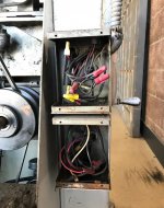
Hmm...I just pulled the covers off the only other electrical boxes on the machine that looked like they were designed to come off somewhat easily and this is where my level of comfort ends...where would this magical transformer be located? There was a nice diagram on the back of the motor plate and clearly labeled wires (albeit dirty, but at least labeled) but in this case all I see is a mess of wires....or are you saying that I just need to figure out what all these wires are connected to and reconfigure them per the diagram you attached?

22 (2).jpg
 
By the way - the quick responses and level of support on this forum is really awesome. I've used a lot of forums over the years and even though I'm a noob here I really appreciate the communities patience and willingness to help.
 
where would this magical transformer be located?

Welder has a few screws to undo and then can be tilted out from top (at least I can on my 1973 machine) to see if anything can be learned. You don't want to pick it up - too heavy, and it won't come out anyway until wires are disconnected. The general idea is to see if there is a transformer in there too. If not, tilt it back up and put the screws back in

Those colorful wire nuts post date 1950 by a bunch of years
 
Last edited:
Yeah - I didn’t attach a photo of the motor wires with the plate off but the nuts on the motor wires were clearly original (not colored and looked like they were from 1950). As you pointed out the nuts in the other two panels are clearly much newer. So these things most likely came prewired for 220V (240V per today’s standard)?

Ive left the office for the day but I’ll pull the welder panel off tomorrow and see what’s behind it. Is there an easy way to test functionality of the welder without welding anything that won’t damage it? Can I just contact it briefly and see if it sparks? The only test I’ve done so far is to flip the switch and watch the grinder wheel spin...which it does with the machine as-is currently wired to 480V.
 
Three more questions on this while I’m thinking about it:
- ML model “rebuild” threads are mentioned in a bunch of other posts here but can anyone point me to one that has the details/instructions and not just pictures of the final rebuild?
- can someone clarify what the blade welder needs? I’ve seen posts referring to 240V 3-phase and 240 single phase. Does anyone know for sure?
- I’ve been able to find the parts manual for this saw from doalls website but does anyone know where I can find documentation telling me how to oil/lubricate and otherwise service/maintain the saw?

First, John Oder has been an enormous amount of help with my DoALL 1612 project. He is full of good data. On your wiring/voltage issue, yes this can be a bit confusing. It seems most of these saws are designed for a 4 wire feed. That is the 3 phases, L1, L2 and L3 and safety ground. Please note neutral is usually not used. The motor can be configured for low or high voltage. Low voltage being 208 to 220 volts. High voltage being 400 to 480 Volts. The welder on the other hand and the control voltage transformer is not adjustable and must be fed with 208/220 Volts. The power relay magnet is operated by 110 Volts from the control voltage transformer secondary winding under the fuse block and the on and off switches. The power relay only powers the motor through the overload monitor. The on/off control runs from one end of the control transformer secondary winding to one of the NC contacts of the off switch. The other off switch contact goes to both one contact of the NO contacts of the on switch and the holding contact of the power relay. From the other end of the holding contact a wire runs to the other contact of the on switch and then on to one of the NC contacts of the power monitor. Lastly, the other contact of the power monitor returns to the other end of the control transformer secondary winding. This circuit is effectively a safety interlock circuit.

I have described this schematic because I have never seen one drawn. So although the motor is switchable between voltages, the rest of the machine is not. I would guess that in the case of any voltage other than 208/220 V, another adjustable transformer must be included like the one drawing John just supplied to power the blade welder and perhaps even the control transformer. It is possible your control transformer is either adjustable or may be a high voltage one. In any case, if you remove the 4 mounting screws for the fuse block, the transformer will be exposed and it will be labeled.

When I stated the welder is a 220 volt welder. I mean it can be fed with either a phase to phase (208 V) connection from a 3 phase source or a phase to phase connection (240 V) from a single phase source or a phase to neutral connection from a 400 V 3 phase source. All of which will work.


Back
Top