Mud
Diamond
- Joined
- May 20, 2002
- Location
- South Central PA
Follow along with the video below to see how to install our site as a web app on your home screen.
Note: This feature may not be available in some browsers.
... I would have liked to see how he did the cam ring to work the valves.
Most of the parts are fairly straight forward but I would have liked to see how he did the cam ring to work the valves . The cam ring rotates at a fraction of engine speed not 1/2 of crank speed like a automotive engine.
Also, how does crankcase lube work? I know you have to "Pull Thu" a radial engine to clear oil from the lower cylinders but...............
Rick
1/8 crank speed on the nine cylinder. Totaly differing in concept - the lobes serving multiple cylinders in turn.
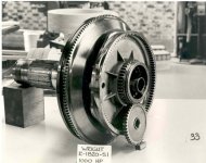
Added early Wright 1820 photos. This is the late thirties "G" Cyclone with 1000 HP - when they still had forged Aluminum crankcases - possibly the first engines used on the B17 - geared nose of course. The ring with the lumps is the cam
John,
I'm familiar enough with the innards of radial engines to know that the cam ring is a comparatively sophisticated piece of work. I would be interested in seeing how the builder machined that particular component.
Which leads to a couple of questions: What equipment did P&WA or Wright use to manufacture the cam rings back in the day, and, having already arrived at suitable lobe profiles, how would you personally go about making one using manual equipment?
~TW~
What happens to the valve train oil. Does it just fly away into the wind. I have seen old cars with exposed valve trains like that. They quickly designed covers to keep out rain and dirt and to keep the oil in. Is it legal to fly with a home made engine like this?
Bil lD.
So how does the valvetrain get lubricated?
Also, that's a pretty fancy home machine shop, what with CNC stuff all around....
I'm wondering what keeps the thing from dragging itself away. Suppose the prop isn't designed to create much... what do you call it? "Pull"?
Is it legal to fly with a home made engine like this?
Bil lD.
I'm wondering what keeps the thing from dragging itself away. Suppose the prop isn't designed to create much... what do you call it? "Pull"?
I think 'thrust' is used when talking about jet engines. These end up 'pushing'. A prop pulls the plane, I think. That's why I didn't use 'thrust'. I could be completely wrong about everything I just said.............I belive that "thrust" is the word that is used to measure the forces of an airplane engine.
Notice
This website or its third-party tools process personal data (e.g. browsing data or IP addresses) and use cookies or other identifiers, which are necessary for its functioning and required to achieve the purposes illustrated in the cookie policy. To learn more, please refer to the cookie policy. In case of sale of your personal information, you may opt out by sending us an email via our Contact Us page. To find out more about the categories of personal information collected and the purposes for which such information will be used, please refer to our privacy policy. You accept the use of cookies or other identifiers by closing or dismissing this notice, by scrolling this page, by clicking a link or button or by continuing to browse otherwise.