What's new
What's new

How to locate the top on a part at 45 degrees?

SpencerFTO

Plastic
Joined
Jun 29, 2020
Hey there,

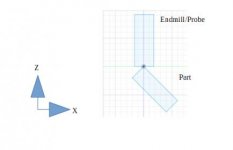
I'm using a mini-mill (Minitech GX mill: Mini-Mill/GX - MINITECH MACHINERY CORPORATION) to machine tiny grooves into parts. I'm new to milling (been learning the machine for the last couple months). The grooves are 90 degree cuts, we call them v-grooves. The company has decided that the easiest way is to use an endmill with the part tilted up to 45 degrees (we have a trunnion table on the mill). This angle makes locating difficult. I've read about using 1-2-3 blocks or paper as a sort of feeler, but this won't really work on a top edge.

My question is this: What is the easiest way to accurately locate the top of the part? The highest point on the part is the top corner edge, and I've been bringing the tool (0.040" endmill) closer and closer until I feel it catch or until I can't see light through, but this seems very inaccurate.

The parts we make are ~7mm across and the v-grooves are all under 0.3mm across them (or 0.3mm spacing).

Thanks for any tips!
S
 
If you can get to the part with a height gage, use it to find the top of the part. Then just set your tool to the height gage.
 
I'm also not in a machine shop. Our set up here is pretty limited, so no height gage unfortunately.
I've thought about the math suggestion, but not sure exactly how that would work. The axis of the trunnion isn't marked and the part doesn't sit in line with the axis. GENERALDISARRAY could you expand?

Thanks for the quick replies! That's awesome!
S
 
Toolroom guy has it nailed. For better accuracy, use an indicator in the spindle to pick up the center of the roll, but that method is universally how it is done.
 
Probably the easiest way would be to use a pin with a 45 or 60 degree point in place of the end mill and line up the point with the top edge. Then replace with the end mill and touch to get the Z, then use trig for X and Z coordinates for each cut.
 
Toolroomguy: I don't really understand the method you're describing. I think that I may not have fully explained what my setup is like, so here's a drawing:Setup Drawing.png It seems to me that you're talking about locating an edge at 45 degrees in the x-y plane, but I'm talking in the y-z plane.

Scottl: I think that drawing will also help to clarify your answer for me too. I'm asking about the best way to touch off off the z. Touching the corner with a 1/8" probe or a 0.040" endmill isn't easy (or I'm doing it wrong).

Thanks again for all the replies, I'm very happy to keep on learning!
S
 

Attachments

  • Setup Drawing.jpg
    Setup Drawing.jpg
    7.5 KB · Views: 115
Since you aren't in a machine shop environment (if I read that correctly) how are you inspecting the work when finished? If you aren't inspecting, I think your original method of using the tool to touch the top corner is fine.

Do these grooves require some accuracy to the edge of part? The spacing should be repeatable with a readout, or programming a Z move in between grooves...
 
We inspect the work with a very large magnification microscope. The grooves are only ~0.191mm deep or less, so inspection otherwise would be tough. Also they're used for very fine work, so as we use them we can tell if they're out or not.

The accuracy is that they need to be centered on the part. I trust my spacing 100%, with the CNC I can move the z and y down and out the same amount and the cuts are pretty much perfect. The only issue is that they are all ~0.75mm or more too close to the bottom of the part, not centered. This means that the grooves at the end run off of the part. It's an issue because I need to run quite a few of these and if I can't locate on one I won't be able to accurately locate any of them. (The part is about 7mm across with grooves in the middle, and equal sized flats on both sides).
 
Sometimes the fastest way to do the job is get close and let inspection tell you which way to move. If material cost is significant, make a dummy part from cheap material or use a scrap part from a previous operation. If just a dummy or scrap part, make a big hole so it doesn't get mixed up with the good parts. Serialize all scrap or set-up parts so you will know for certain you have them all before shipping the good parts.
 
If the part geometry allows, make soft jaws with pockets for the part to fit into snugly. If the soft jaws are accurately made all around, you can then indicate off of a corner of one of the soft jaws to know where the part is.

Like this:

Soft jaw pocket.jpg

Regards.

Mike
 
The pin against a block method shown by toolroomguy is all you need. That will locate the machine in both X (or Y) and Z axes. If you have a probe on the machine, use it to pick up both X (or Y) and Z. If not, edge find the pin for X or Y, then touch off on the pin with the tool for Z. Use a piece of paper or a feeler gage if you need to.
 
Sometimes the fastest way to do the job is get close and let inspection tell you which way to move. If material cost is significant, make a dummy part from cheap material or use a scrap part from a previous operation. If just a dummy or scrap part, make a big hole so it doesn't get mixed up with the good parts. Serialize all scrap or set-up parts so you will know for certain you have them all before shipping the good parts.

This ^ is what we typically do. Our parts are aluminum and brass so material isn't an issue. We are trying to hit tenths on parts that are about .4x1x2 with a buttload of pockets and twisty corners, hard to check in the machine so it comes out of machine to the micro-vu and tenths indicators.
 
Thanks for the replies everyone. I don't know if I wasn't clear enough, but our parts are under 6mm x 3mm (.25"x0.125"), so using an edgefinder isn't possible (also on the minimill, the spindle is too small to hold one). When I edge-find I use a precision probe and put dry erase marker on it, then move it closer and closer to part, turning by hand, until marker rubs off. Do this at smaller and smaller intervals.

I have been using scrap to practice so far, then have to do the real one later (we work on parts shipped by customer, so taking time to perfect it before messing up their expensive part).

I can't edge-find the left side of my drawing because it is sitting in a fixture. These tiny parts don't sit well on parallels so I milled a small seat for it, and the top and left edges locate (so the corner is under the fixture).

My best result so far came from using the probe and lowering it in the z-axis with a brass shim underneath till it caught, then moving down the depth of the shim and zeroing.

Thank you for all of the replies!
S

If you're using a fixture, then you should be locating off the fixture. Add a tooling ball to the fixture. Then you will only need to locate the top of the part once, using toolroomguy's suggestion. From there it's simple to calculate the offsets to the tooling ball. Next time you run the job you just indicate the tooling ball for x-y-z. Hope this helps.

Best Regards,
Bob
 
Can someone explain toolroomguy's idea a little more? I really don't understand it and a lot of you are referencing it.

Thanks!
S
 
What he's showing you in that drawing is three things, if I'm not mistaken:
1) A triangle pointing up. That's your part pointing up, correct?
2) A setup block or anything with a flat side on it. It is laying flat on one of your 45deg sides.
3) A dowel pin of appropriate size laying on both the other 45deg surface and the ground block mentioned above.

When you edgefind the outside diameter of the dowel pin, you will then be able to calculate how much to move in order to be right over the top of your part.
Also, you will be able to touch your cutter to the top of the dowel pin and calculate how far down to set your Z0.


Back
Top