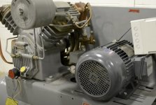
early 2000's T30 compressor that came with a bunch of stuff I bought is not performing. It takes way too long to get up to it's 170 psi cutoff and can't keep up with even minor demand. This one has a hydraulic or "suction" unloader that seems to be doing what it should. There is a port fitting like for a copper compression fitting on the low pressure head that has nothing connected (and nowhere has a place for a line from there to attach to), maybe that's supposed to be pressurized to seal the unloader? I've never had one of these apart; is there a common issue this might be or is it more likely to just be worn out? I didn't try to remove the oil cap while it was running to check for massive blowby yet, but I'm thinking maybe it might have a bad reed valve or something. Any suggestions would be appreciated
How to install the app on iOS
Follow along with the video below to see how to install our site as a web app on your home screen.
Note: This feature may not be available in some browsers.
Largest Manufacturing Technology Community on the Web
Stay Connected:
You are using an out of date browser. It may not display this or other websites correctly.
You should upgrade or use an alternative browser.
You should upgrade or use an alternative browser.
Ingersoll Rand 2545 (t30) low output cfm
- Thread starter tomjelly
- Start date
- Replies 13
- Views 2,057
eKretz
Diamond; Mod Squad
- Joined
- Mar 27, 2005
- Location
- Northwest Indiana, USA
Pretty sure those compression fittings should be connected to something for the unloader to work properly. Are you losing air there?
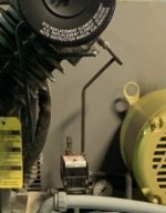
No air comes out of there, running or not. Looking at various diagrams on the web it looks like that would be attached to what I think they call an auxiliary valve that can switch the unit between continuous and intermittent running. My machine does not have such a valve, only an electric pressure switch that controls the motor. The pressure switch doesn't even have the usual schrader unloader feature, I guess because it has the unloader in the head. There is some sort of large shuttle valve in the intake, can't really be sure of how it works until I take off the head. Maybe because this unit had no aux valve (and was only ever made to cycle on and off) it would never have had anything to that port. Very weird that it has a fitting in it though, as it is a perfect spot for mud daubers to fill, doesn't seem right. In the attached photo from the web you can see the line I'm referring to it runs from the head and curves upward then down to the valve body above the pressure switch. I don't have that valve body.
Attachments
eKretz
Diamond; Mod Squad
- Joined
- Mar 27, 2005
- Location
- Northwest Indiana, USA
Ahh, so you don't use the unloader? I guess it wouldn't be important to plug it then. IIRC the unloader ports are sort of like an air-powered switch. When air pressure hits that line it either opens or closes the valve. I have a 3 cylinder 47cfm head that is waiting for adaptation to a tank and it has unloaders - I did some looking into how they work but it was a while back. I think you'll need to leave it open/unpressurized to allow the head to pump up pressure. Might want to disassemble and see if anything is sticking. Somebody else will know the system better than I do, I'm sure. You could always remove the fitting and put one of those metal sponge filter things there instead to keep unwanted debris out.
You read my mind about the sintered metal filter. So if pressure is NOT applied to that fitting the compressor should build pressure, right? That would be a good thing as if that is the way its supposed to work I wouldn't want air to there anyway if that is the case maybe that valve is stuck or gummed up, for all I know there IS a mud dauber deep in there, clogging up the works. I'm going to take off the heads so I can check that out as well as inspect the reed valves tomorrow.
eKretz
Diamond; Mod Squad
- Joined
- Mar 27, 2005
- Location
- Northwest Indiana, USA
You read my mind about the sintered metal filter. So if pressure is NOT applied to that fitting the compressor should build pressure, right? That would be a good thing as if that is the way its supposed to work I wouldn't want air to there anyway if that is the case maybe that valve is stuck or gummed up, for all I know there IS a mud dauber deep in there, clogging up the works. I'm going to take off the heads so I can check that out as well as inspect the reed valves tomorrow.
I think it depends on the exact compressor and valve setup. I would investigate the valve and see how it works, where the passages go, how the valve moves and what gets blocked/opened when it does, etc. Disassembly and examination should give you the answer. I think on mine, air pressure to the valve is needed when it's pumping, then it is bled off afterward. If yours is that way, it may explain why it's taking longer to pump up. I was thinking yours maybe worked the opposite since you mentioned it was open and it worked, but perhaps it's not fully working as it ought to be.
I was going to try to apply air to that port with a blowgun nozzle while running and see what happens, but I think I'll take the head off the verify how that system works before I screw something up. From the diagrams on the web it looks like it should come apart easily and not require any new parts to put it back together
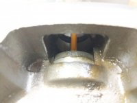
I took the head off. First, the reason its pumping so slowly is that the discharge finger (reed valve) seats in the low pressure valve plate were all badly corroded and thus not able to seal. The mystery port, when pressurized, shuts off the intake from the air filter. Looks like in continuous run applications you'd need to pressurize that port to allow the motor to run and yet not pump anything, whereas in my application where the motor shuts off the pressure is not needed to seal the intake. That fitting has a tiny orfice in it so although nothing could theoretically get in there, I'm going to put a sintered filter in anyway. knockoff valve plates complete with reed sets are $71 on Ebay, still waiting on OEM pricing from IR.
in photo 3 I've opened the intake valve by pushing thru the air filter inlet with a pencil. This would be the position of the valve when the compressor is sucking in air. photo 4 is the position the valve would be in if pressure was applied to the mystery port with the small orfice, closing off the intake. the port at the very top of photo 5 just dumps into the air filter area, and the port near the mystery port with the tee fitting on it leads to the intake side of the inside of the head. I'm still not sure how the pump unloads in my application though, maybe someone can explain that to me!- I'm hoping this pump is REALLY unloading somehow rather than SEEMING like it was unloaded because of the fact that the valve plate was not sealing.
in photo 3 I've opened the intake valve by pushing thru the air filter inlet with a pencil. This would be the position of the valve when the compressor is sucking in air. photo 4 is the position the valve would be in if pressure was applied to the mystery port with the small orfice, closing off the intake. the port at the very top of photo 5 just dumps into the air filter area, and the port near the mystery port with the tee fitting on it leads to the intake side of the inside of the head. I'm still not sure how the pump unloads in my application though, maybe someone can explain that to me!- I'm hoping this pump is REALLY unloading somehow rather than SEEMING like it was unloaded because of the fact that the valve plate was not sealing.
Attachments


eKretz
Diamond; Mod Squad
- Joined
- Mar 27, 2005
- Location
- Northwest Indiana, USA
I took the head off. First, the reason its pumping so slowly is that the discharge finger (reed valve) seats in the low pressure valve plate were all badly corroded and thus not able to seal. The mystery port, when pressurized, shuts off the intake from the air filter. Looks like in continuous run applications you'd need to pressurize that port to allow the motor to run and yet not pump anything, whereas in my application where the motor shuts off the pressure is not needed to seal the intake. That fitting has a tiny orfice in it so although nothing could theoretically get in there, I'm going to put a sintered filter in anyway. knockoff valve plates complete with reed sets are $71 on Ebay, still waiting on OEM pricing from IR.
in photo 3 I've opened the intake valve by pushing thru the air filter inlet with a pencil. This would be the position of the valve when the compressor is sucking in air. photo 4 is the position the valve would be in if pressure was applied to the mystery port with the small orfice, closing off the intake. the port at the very top of photo 5 just dumps into the air filter area, and the port near the mystery port with the tee fitting on it leads to the intake side of the inside of the head. I'm still not sure how the pump unloads in my application though, maybe someone can explain that to me!- I'm hoping this pump is REALLY unloading somehow rather than SEEMING like it was unloaded because of the fact that the valve plate was not sealing.
Generally the unloader is built into the pressure switch when the head unloaders aren't used. Does it hiss/bleed down after it shuts off?
The pressure switch does NOT have an unloader on it (type that has a schrader valve pusher that dumps the pressure between the pump and tank when the motor cuts off) Whatever unloading that this thing does is (I guess) somehow done with the small tubing pipework or maybe something inside the front of the crankshaft. Either that or its missing. I don't know how that would work but would like to know so when I get the head back together I know it will work properly or that I need to CHANGE the pressure switch to one WITH an unloader feature, then tee in the associated tube from there to the pump to tank line. I'm assuming the pump does the unloading somehow only because there is no unloader on the switch, which appears original
eKretz
Diamond; Mod Squad
- Joined
- Mar 27, 2005
- Location
- Northwest Indiana, USA
2545 pdf I just looked up seems to show one setup as a centrifugal unloader attached to the crankshaft, maybe that's what you've got? There's also a hydraulic one controlled by oil pressure like you mentioned on the pressurized oil systems. Either way I'd expect to hear the line bleed down when it unloads. Do you have the pdf manual so you can compare parts present?
I don't have the parts breakdown for this particular pump; I was only given the subassembly drawings when inquiring with IR about the valve plate. There must be the crank setup you describe- looks like it (see the attached picture of my unit- that crushed tube and line to the check valve have since been replaced), but I'm pretty sure I did not hear it blow down when shutting off. Maybe it was just bleeding down past the leaky corroded low pressure valve plate (though I don't know if the low pressure side would "see" that pressure)
Attachments

I know this is a few years too late, but you have a centrifugal unloader on that pump. The 1/4" tube that runs from the high pressure head side to the elbow on the front of the crankcase has a valve in it (called the pilot valve) that is opened when the pump stops, this unloads the heads through the tube that runs to the flange that the air filter is attached to. The unloading is pretty quiet on this pump because it is muffled by the air filter. If you remove the filter housing you can hear it better. If it doesn't unload at all, try removing the 1/4" elbow that attaches to the air filter flange and inspecting it, mine was full of rust, and wouldn't drain.I don't have the parts breakdown for this particular pump; I was only given the subassembly drawings when inquiring with IR about the valve plate. There must be the crank setup you describe- looks like it (see the attached picture of my unit- that crushed tube and line to the check valve have since been replaced), but I'm pretty sure I did not hear it blow down when shutting off. Maybe it was just bleeding down past the leaky corroded low pressure valve plate (though I don't know if the low pressure side would "see" that pressure)
Posting this for anyone that comes across it in the future.
Similar threads
- Replies
- 0
- Views
- 181