What's new
What's new

Interferance Fit Steel -> Alum for Welding Jig

JD Tek

Plastic
Joined
Feb 8, 2019
Working on a welding jig to speed up production, it will hold .75" square steel tubing. I have prototyped it in Foam / MDF before I move to the more expensive 6061-T6 Aluminum. I want a tight fit for the steel to sit in the aluminum so the pieces can stay in place for welding, but not so tight that its a pain / takes up time to remove them.

When I prototyped in foam I didn't give any offset / add anything for tolerance... just kept it the same .75" and it fit very nicely, I think because the foam material is very soft... With MDF I did the same and the fit was a little tight. I imagine with Aluminum it will be even tighter so I will have to add a little bit of offset. If I remember right I got some good results doing an offset of .015" with MDF jig once.

In your experience what works well for aluminum? I saw a calculator on the net but it seemed a little more complex than what I was looking for.

I could try just milling one small piece and fitting, but it is pretty expensive for me, getting some ideas will help for starting point.

Thank you!
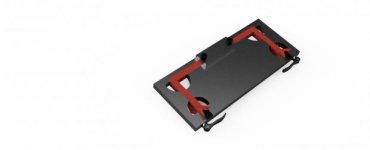
jig v3 v113.jpg
jig v3 v10.jpg
 
Take a look at the tolerances on the outside dimensions of the tubing. At least +-.003 inches.
In aluminum your nest will range from loose and rattling, to bang it in with a sledge.
You need to design a fixture with a rigid reference edge and some adjustable or compliant biasing on the opposite side. The foam and mdf work because they are low rate springs compared to Aluminum.
 
- use the largest tolerances you can

- make one side of the fixture fixed and use something like de-sta-co clamps on the other to push the material in place. Fixed jigs that surround your material are an absolute pain in the ass
 
Aluminum is expensive and it wears over time. Your tubes should be resting on short bars or edges at key locations and as mentioned a clamp or cam action should push the tube against the edges. Those edges would be something like half inch key stock tacked on the base and short pieces of flat bar cut square standing vertical.
When everything is welded on the fixture the spatter can fall away onto the plate. The spatter does not end up on the reference edges and when your clamps are released everything lifts away easily since it is only resting on those edges.
You spray antispatter on the table to make brushing away spatter easy. Before loading the operator only has to ensure that his reference edges have not pickup up spatter which is next to impossible.
Looking at the picture you would have six reference edge locations and three cam/clamps. You would then need a few reference edges for the fitting at each leg and one cam/clamp for each.
Having the weldment fit perfectly in a sliding fit to the fixture ends up troublesome when removing then finally operators resort to hammers, wedges and pry bars. Once it is out then they look at you with a blank stare and say "Well it was square when I welded it up in the jig."
 
I build jigs from steel but I use aluminum spacers for tight fits. This allows me to have a heavy duty steel jig, but aluminum flat bar spacers to keep spatter to a minimum and easily it adjustable for tubing that is a little thicker or thinner.

Sent from my SM-G960U using Tapatalk
 
Make sure all your reference faces are in only one direction, you need to be able to move the welded assembly out in one direction, a square cornered part could pull away at 45 degrees out of the jig.

Make the jig so you can compensate for distortion, if the part is comming out skew put it in skew so it comes out straight,
Hope that makes sense!

Sent from my SM-G950F using Tapatalk
 
I ended up redesigning the entire jig after the feedback I got... this is what I ended up creating:

Thanks for the feedback!

Jeff
 
Get yourself a Carr Lane catalog.

It will have 99% of what you need for the next one, and
it will improve your fixture designs greatly.


Back
Top