What's new
What's new

Which Lathe Taper Attachement Would You Build?

Phase

Cast Iron
Joined
Dec 16, 2010
Location
NJ
Hi,

If you were building it from scratch (a) which design would you pick and (b) which design would offer the best results in terms of the tapers being cut?

Design #1 is the one that attaches to the bed.
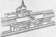
Fig-121-Taper-Attachment-built-by-the-New-Haven.jpg

Design #2 is the one that attaches to the saddle.
Fig-120-Taper-Attachment-built-by-the-Hendey.jpg

This is for a 14"x40" 2500 lbs lathe. The tools I have are a CNC mill with a 20"x18" envelope and a surface grinder with a 20"x6" envelope. I would probably build it off cold rolled stock 1/2" thick (cuz, why not)

Thoughts?
 
All TAs attach to the bed in some fashion. The advantage of the clamp and linkage design is drag on the bed is less. The biggest design difference is whether you wish to use the cross feed screw in both cases of lathe use.(taper and non-taper work) In the drawn example, similar to the small SB lathe TA, you cannot. In that case, you must disconnect the slide from the screw and feed only with the compound. More professional TAs use a differential cross feed arrangement that does not disable the cross feed function. The conversion of non-TA lathes to TA lathes is no small task. Even the installation of factory parts is a first class pain. It is very difficult to achieve a near zero friction difference between the two use cases. Making all the required parts in a one off conversion will cost more in labor than buying a factory made and installed TA.
 
Both shown are obsolete, having no upper support, so fail the "best" test

Good ones - since almost one hundred years now - are BOXED

Scan from mid twenties

Note the UPPER braces in thumbnail

Greaves Klusman (around the corner from L&S) let no grass grow under its feet - photo thumbnail shows the great upper cast brace, also mid twenties
 

Attachments

  • Oil Country TA.jpg
    Oil Country TA.jpg
    90.9 KB · Views: 453
  • 100_1963.jpg
    100_1963.jpg
    91.1 KB · Views: 346
Hi

My lathe also needs a taper attachment.
I think the best solution is to fit an electronic taper attachment.

Probably better to think of it as a copy attachment. Instead of following a template like the old hydraulic versions, have it follow an electronic template.

This would be implemented by fitting a DRO and using this as an input to the control system. Also fit a servo/stepper motor and ball screw to the cross slide. This is hybrid CNC.

This would require a lot less metal work to make than a purely mechanical device, and would be much more versatile.
 
Wouldn´t be a build, but you could also look around for a hydraulic copy attachment.

That would be the cheapest, simplest, and most versatile solution. I've cut a few tapers this way and it always worked out great. Tracers are very underrated in my opinion. A decent tracer setup can usually be found for cheap because of their "obsolescence", and you'll never regret having one.
 
"I would probably build it off cold rolled stock 1/2" thick (cuz, why not)"

Cuz-- of the stresses from the cold rolling leading it to warp, and CRS is not a good bearing material.

If you are going to go to all of the work to make one- consider cast iron- at least for the sliding surfaces.
Lots of other metals would be better than CRS with regard to surface finish and stability.
 
Last edited:
While you're in design phase another choice is whether you want to do the telescoping leadscrew.

I just checked to see if I could get a replacement crossfeed screw, but they are no longer available. So I would need to either mess with my existing screw, find something close, or make a new one. I may open it up to see which section would need to be sleeved and if that could be done relatively safely, but it seems a bit more that I can bite at this time. The disconnect of the lead screw is really simple. There is am M6 screw on the top of the cross slide and you just remove it. There are no nuts falling off the bottom or anything. The nut remains in place so when it is time to connect it back you just move the crossfeed in or out till it lines up and screw it back in place.


All TAs attach to the bed in some fashion. The advantage of the clamp and linkage design is drag on the bed is less. The biggest design difference is whether you wish to use the cross feed screw in both cases of lathe use.(taper and non-taper work) In the drawn example, similar to the small SB lathe TA, you cannot. In that case, you must disconnect the slide from the screw and feed only with the compound. More professional TAs use a differential cross feed arrangement that does not disable the cross feed function. The conversion of non-TA lathes to TA lathes is no small task. Even the installation of factory parts is a first class pain. It is very difficult to achieve a near zero friction difference between the two use cases. Making all the required parts in a one off conversion will cost more in labor than buying a factory made and installed TA.

The original TA is no longer available. I have searched for it a few times and never found anyone getting rid of one. The conversion of the cross feed screw is probably a little bit risky given that a spare screw is not readily available, plus the disconnecting/connecting is easily done. From the responses in this thread I think I'll be doing the clamp and linkage design. Thanks!


Both shown are obsolete, having no upper support, so fail the "best" test. Good ones - since almost one hundred years now - are BOXED. Scan from mid twenties. Note the UPPER braces in thumbnail. Greaves Klusman (around the corner from L&S) let no grass grow under its feet - photo thumbnail shows the great upper cast brace, also mid twenties

I like it. Thank you very much!


See this posting on making a lathe taper attachment.

Vlad

Hi Vlad. I clicked but I found no link.


Wouldn´t be a build, but you could also look around for a hydraulic copy attachment.

My google-fu not so good -- could not find one in decent shape. One thing is that the lathe has a splash guard leaving only around 15" or 17" between the spindle and the sheetmetal at the back. I'll keep an eye out for one though. Thanks!
 
Last edited:


Back
Top