What's new
What's new

Machining Part Help!! Slitting Saw on Vertical Rotary Table

B1gN1ck

Plastic
Joined
Jan 6, 2021
Hello,

I'm new to the forum so forgive me if this post is in the wrong section. I need a part to be made, but the local machine shops all seem to not want to quote this job. I asked a couple of them and they all seem to say it is too difficult to machine. I tried to attach a drawing of the part and a hand sketch of how i would machine it. I've done basic machining in the past, but this one does seem a bit challenging. Please let me know how you think it should be machined.

Please note that the part will be clamped between two plates so if the part springs to a non-flat shape, it will still be okay.

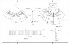
Slitting Saw.jpg
Part.jpg

Thanks,
Nick
 
I forgot to mention a machine shop used was able to make this part in the past but they since shutdown.
 
Sure is a shame you Need that Section B-B R.50 feature.

Otherwise it could be a simple part done flat, top and bottom with a fairly small end mill. ( 10X depth/diameter ratio..)
Granted you could program the tool path to profile that R.50 feature if it really is needed.

I wonder what kind of material this is?
 
It seems like someone may have added that feature or at least included it thinking this would have to be sawed. Looks kind of like a custom resonant chamber for a magnatron tube.
 
Sure is a shame you Need that Section B-B R.50 feature.

Otherwise it could be a simple part done flat, top and bottom with a fairly small end mill. ( 10X depth/diameter ratio..)
Granted you could program the tool path to profile that R.50 feature if it really is needed.

I wonder what kind of material this is?

Oh, come on. The first drawing obviously specifies cnc or mill, specifically shows it can move left or right, uses a "custom" arbor extension that wants 1/2" on a 3/8" shaft, in conjunction with a rotary, that, according to the arrows, can rotate in two directions.
 
So you’re looking at a 1” diameter slitting saw riding on a 4” long, <1/4” diameter arbor.

Good luck. Unless you want it made out of cheese or something.
 
Please note that the part will be clamped between two plates so if the part springs to a non-flat shape, it will still be okay.


Thanks,
Nick

If that is true, then get rid of your two flat to .0005 callouts. Put a more reasonable call out.
Those callouts tell the machinist that any warpage after cutting all those slots is unacceptable.
Now he is trying to figure out how to grind it flat after cutting the slots AND hitting overall thickness and the tolerance on the bottom of the slot.
And you wonder why you are getting no bids........
 
Sure is a shame you Need that Section B-B R.50 feature.

Otherwise it could be a simple part done flat, top and bottom with a fairly small end mill. ( 10X depth/diameter ratio..)
Granted you could program the tool path to profile that R.50 feature if it really is needed.

I wonder what kind of material this is?


Material is 303 SS.
 
Thank you for the help. i will remove those callouts and put something else there instead. Again, i am working with someone else's drawing that was done 20 years ago. I'm just trying to have it remade.
 
When I first looked at the drawing and all the "what if this happens, can I save it" I wondered, do you have a sample of one that meets ALL of the criteria of the posted drawing?
 
This shouldn't be that difficult with the right tooling. The question is, are you prepared to pay for it. It's a shame that you weren't able to procure the tooling from the shop that shut down before they were gone.

The cost of the tooling will be high for a single piece, that is probably part of the reluctance of shops to do it. You may be better off asking to purchase the tooling yourself and only pay for their labor. Then you take the tooling with you and bring it back next time the job needs done - that way you can take it to other shops if necessary also.
 
Observations:

First, I think the first, hand drawing is simply his idea about how to make the part, not any kind of requirement or specification. And, if I am reading it correctly, the diameter of the slitting saw arbor's shank is not less than 1/4", it is shown as a 3/8" diameter. Since the slots are only 0.020" deep, that shank diameter could be as much as 0.530" without any interference.

I see a lot of angles and radii on the drawing, but the overall size (left-right on the drawing) of part is not shown either as an angle, which would be most natural or as a linear dimension. The slots on the second side cover a full 90 degree angle, so it must be larger than that, but how much larger? And is that important? Tolerance?

And edges, any chamfer or radius spec?

How many? How soon do you need them? And would you be willing to do the first one on a time and materials basis so the actual cost to make them could be found? I might be willing to give it a try if my time and expenses were paid, UP FRONT.
 
Do you know for sure the original shop was using a long arbor as sketched or is that your suggestion?
I wonder if they were actually using something like an Aeon projection tool for the saw. (And I’ll state up front that while mine is Aeon brand, I don’t know what the proper tool description is).

Anyway, at a pinch I believe the small Aeon arm could be modified to run a 1” dia saw & a smaller cog procured to drive it - if the price/volume supported doing so. Stock, I think it could run 1-1/2” for that part; certainly 1-3/4”. (.75 to .875 R)

I gather the saw is being run in alternately from the front and then back? As opposed to running 1/2 & then flipping and re-registering the part?

As has been noted there is some tooling cost, set up time & experiments on scrap before the first good part is made

Open to being contacted, too.
At least to discuss application and what is really critical for features & tolerance.

e h m co fab at g male

smt
 
And, if I am reading it correctly, the diameter of the slitting saw arbor's shank is not less than 1/4", it is shown as a 3/8" diameter. Since the slots are only 0.020" deep, that shank diameter could be as much as 0.530" without any interference.

Sure, but that ignores the plate that he wants clamped on the front, or any other fixturing that will surely interfere with the arbor.

IMO this could be made a lot more manufacturable with some small engineering changes. E.g. increase that radius to 0.75”.
 
The plate will be clamped on after it is machined, when the part is in use. That's why he's saying it doesn't matter if the part springs a bit during machining... So yes, a ½" saw arbor should be fine.
 
Very neat.......

And no one thought about purchasing the tooling for the part?

Unfortunately no. I don't think it was known that they shutdown until we asked for more. Would've been nice though.
 
This shouldn't be that difficult with the right tooling. The question is, are you prepared to pay for it. It's a shame that you weren't able to procure the tooling from the shop that shut down before they were gone.

The cost of the tooling will be high for a single piece, that is probably part of the reluctance of shops to do it. You may be better off asking to purchase the tooling yourself and only pay for their labor. Then you take the tooling with you and bring it back next time the job needs done - that way you can take it to other shops if necessary also.

Thank you eKretz. That is a question i will have to ask the machine shops. The only problem is we are now trying to fine tune a process that has been half working for a long time. Optimizing it will take a few iterations which only happens with one change at a time. Something to definitely consider.
 
Observations:

First, I think the first, hand drawing is simply his idea about how to make the part, not any kind of requirement or specification. And, if I am reading it correctly, the diameter of the slitting saw arbor's shank is not less than 1/4", it is shown as a 3/8" diameter. Since the slots are only 0.020" deep, that shank diameter could be as much as 0.530" without any interference.

I see a lot of angles and radii on the drawing, but the overall size (left-right on the drawing) of part is not shown either as an angle, which would be most natural or as a linear dimension. The slots on the second side cover a full 90 degree angle, so it must be larger than that, but how much larger? And is that important? Tolerance?

And edges, any chamfer or radius spec?

How many? How soon do you need them? And would you be willing to do the first one on a time and materials basis so the actual cost to make them could be found? I might be willing to give it a try if my time and expenses were paid, UP FRONT.

Hi EPA,

You are correct, the hand drawing is my interpretation of how i thought it could be machined. I am not sure where others got the 1/4", but the slitting saw i found had a 3/8 bore that you understood.

Far left to right dimension is 5.745", but i left this out purposefully as i wanted to protect the company i work for. Realistically the part has more slots in it and is more full (more closed as a circle) but for understanding how this could be machined i modified the part as to not publish our full design. The edges, chamfer, radius specs are all in the title block, which obviously isn't included in this, again to protect the company.

Again, this forum is for me to understand how to machine something like this and understand why machine shops don't want to even touch it. If you are interested in putting in a quote, direct message me your info and i'll shoot you an email from my company email.

Thanks,
Nick


Back
Top