What's new
What's new

Machining the "rotor" of a PatWankel rotary engine

manolis

Aluminum
Joined
Nov 25, 2006
Location
Athens Greece
Hello all.

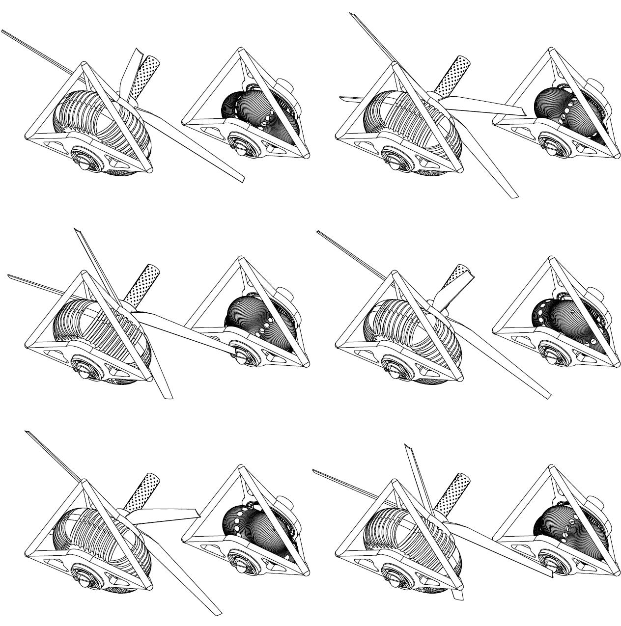
Here is the inner body of an unconventional rotary engine and the way to cut it in a lathe:
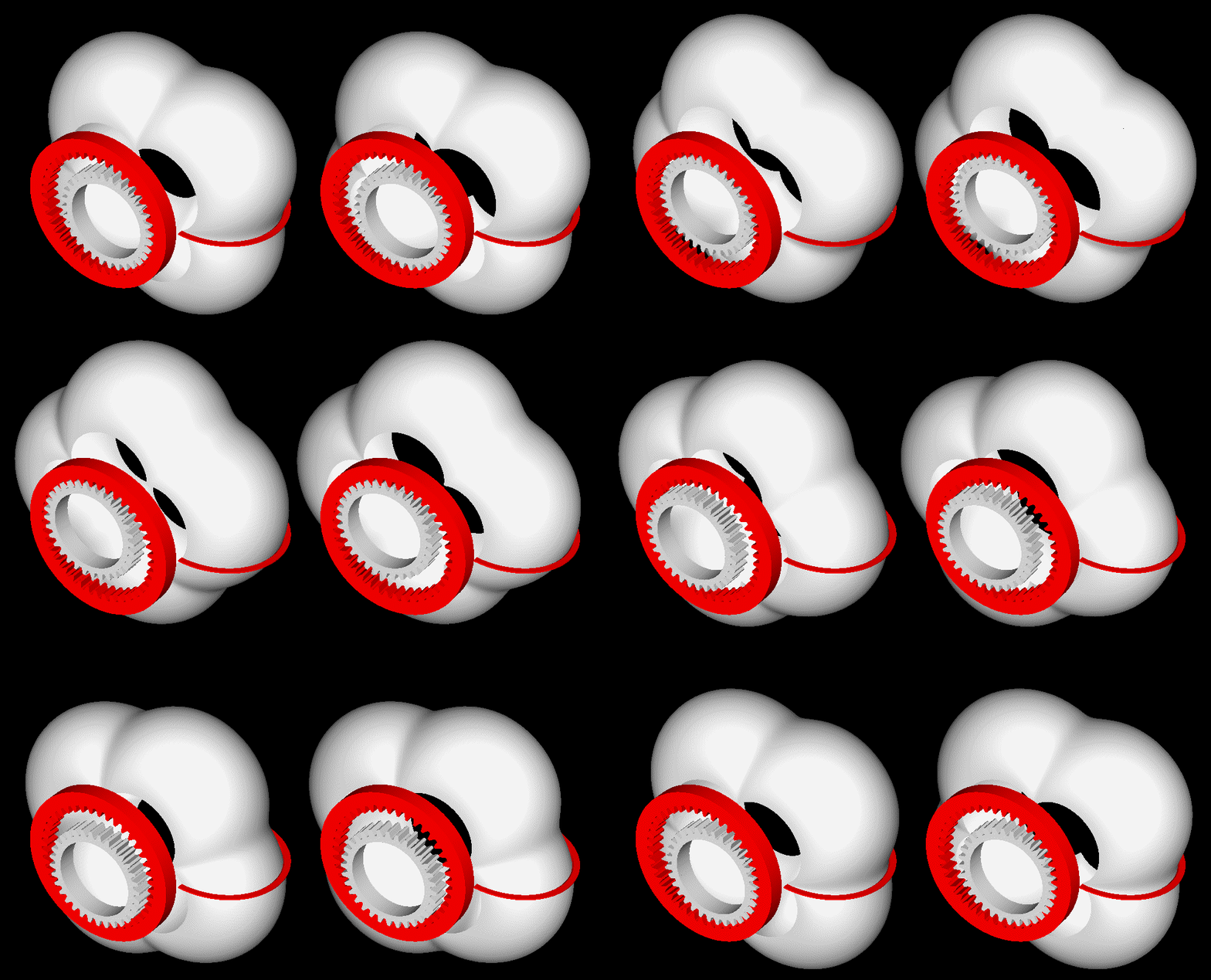
PatWankel_Five_Cut.gif


(instructions in how to see it stereoscopically at http://www.pattakon.com/pattakonStereoscopy.htm )


At operation it would be like:
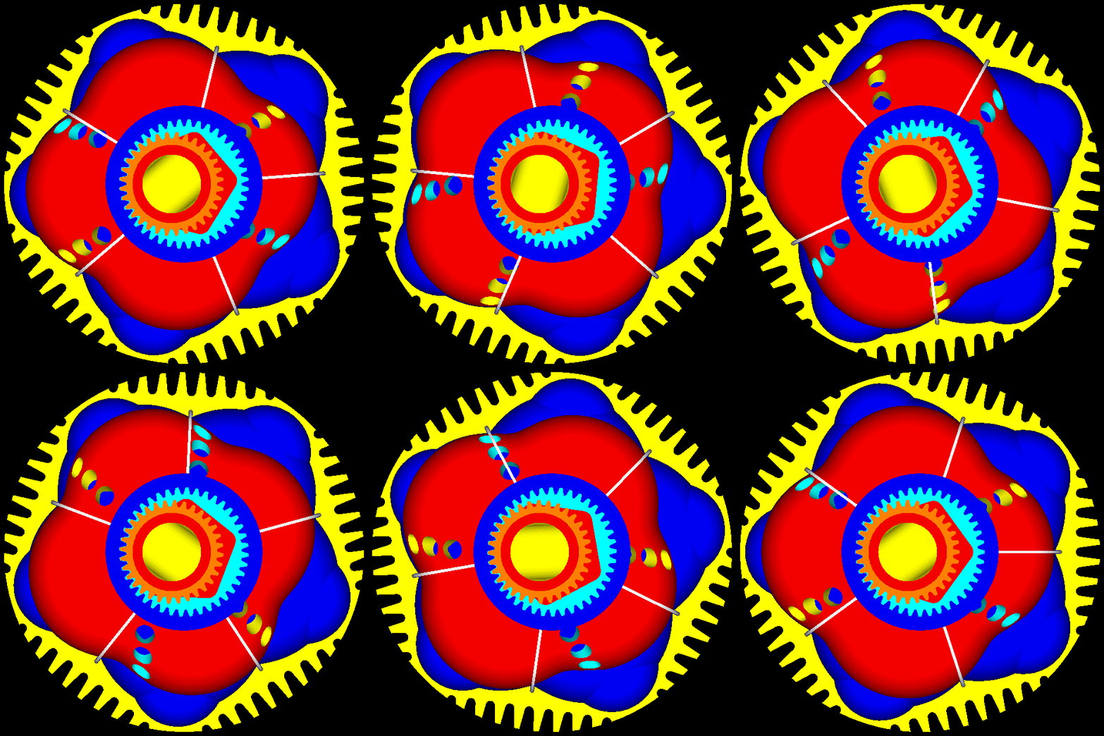
PatWankel_Five_front.gif


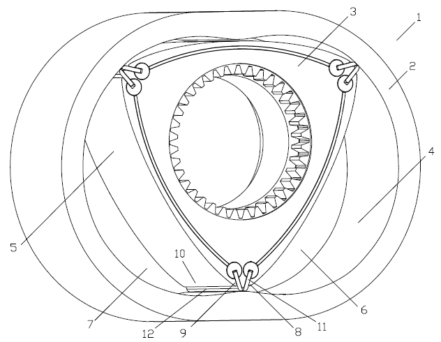
It comprises two only parts, each spinning at constant speed about its own fixed axis (which means perfect balancing without any balance webs).
The eccentric shaft of the Wankel RX8 and of the LiquidPiston rotary engines is eliminated.
The power / torque is delivered by a shaft / extension of the inner body:
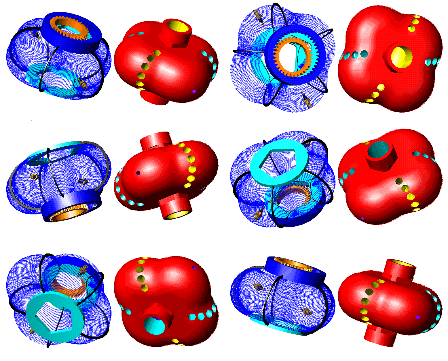
PatWankel_Five_lines.gif


There are two combustions per shaft rotation (i.e. as much as in a Wankel with two rotors).

The big difference is in the sealing.

More about how this engine (PatWankel) operates are at http://www.pattakon.com/pattakonPatWankel.htm


Regarding the machining of the working surface shown in the first animation:

On the chock of a lathe it is secured eccentrically a shaft.
The red gearwheel is secured immovable on the lath bed.
The body with its gearwheel (white) is rotatably mounted on the shaft.
As the chock rotates, the body to be machined performs a combined motion (it spins about the shaft and it orbits together with the shaft).
Given the shape of the seals to be used (the simplest form? the circular), the cutting tool has to follow a specific “path” (like half circle, for instance) in order to create / form the working surface on the part (the working surface is whereon the seals will abut and slide during operation; the seals are mounted in grooves made on the outer body).

In case of seals having simple form, even a conventional (not CNC) lathe can be used.

Similarly for the honing / polishing.

The material is to be either spheroidal graphite iron (as in the cylinder liners).


Thoughts? (like: problems you see)

Thanks
Manolis Pattakos
 
Not unlike the two lobe Cooley Engine. The seals will only make finite line contact (not a great idea) since the angle they subtend to the rotor changes with rotation.

Rotary Steam Engines: Page 6.

>The eccentric shaft of the Wankel RX8 and of the LiquidPiston rotary engines is eliminated.
And that's important because??

It's interesting, but don't loose your shirt trying to develop it ;-)

Bill
 
Hello Jcandlish.

You write:
“Looks hard to cool, with the exhaust gas passing out through the rotor. Has a thermal model been done?”

If the combustion is as bad / slow / incomplete as in the Wankel RX8, and the exhaust gas is as hot as in the Wankel RX8, the PatWankel project is for the scrapyard.


Last month LiquiddPiston received another $2.5 million from the DARPA for their rotary Reverse-Wankel engine ($3.5 million in total, so far).

LiquidPiston took a price from the MIT too.

More interesting: LiquidPiston also received a $25,000 cash prize from the Shikorsky along with the opportunity to explore opportunities for LiquidPiston's technology with the Shikorsky product line


If the PatWankel works / burns not as the Wankel, but as the LiquidPiston, the combustion will be better than Wankel, the expansion will be “overexpansion”, the cycle will be Atkinson-Miller, the compression will be high and the exhaust gas temperature will be way lower (because the energy of the fuel goes in generating mechanical power and not in heating the exhaust gas).


Besides, the exhaust gas needs not to come in contact with the inner walls of the “rotor”. A pipe inside the “rotor” transfers the gas outside, say as in:

PatWankel_Pusher.gif


wherein inside the power shaft (which is an extension of the inner body (or rotor)) it runs a second hot pipe for the exhaust gas.

Thanks
Manolis Pattakos
 
Hello Billtodd

You write:
“Not unlike the two lobe Cooley Engine. The seals will only make finite line contact (not a great idea) since the angle they subtend to the rotor changes with rotation.”


The seals of the Wankel rotary operate this way.

Quote from:
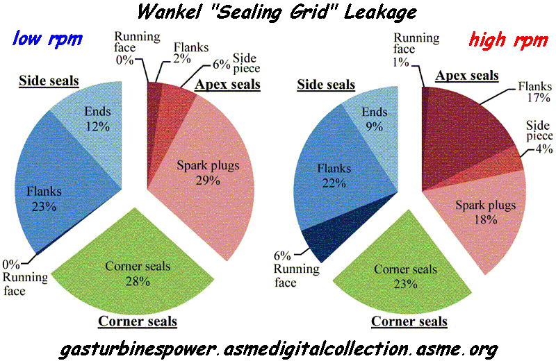
Predicting Gas Leakage in the Rotary Engine—Part II: Side Seals and Summary | Journal of Engineering for Gas Turbines and Power | ASME DC

“Abstract
The Wankel rotary engine offers a greater power density than piston engines, but higher fuel consumption and hydrocarbon emissions, in large part due to poor gas sealing. This paper presents a model for the deformable dynamics of the side seal, which completes a set of modeling tools for the comprehensive assessment of the gas leakage mechanisms in the rotary engine. It is shown that the main leakage mechanisms for the side seals are: (1) opening of the inner flank due to the contact with the trailing corner seal, (2) flow through the gap with the leading corner seal, (3) simultaneous opening of both inner and outer flanks due to body force at high speed, and (4) running face leakage due to nonconformability at high speed. The leakage mechanisms are qualitatively validated at low speed with observed oil patterns on the rotor from laser-induced fluorescence (LIF) experiments. Finally, the predicted total leakage area for all the gas seals ranges from 1.5 mm2/chamber at low speeds to 2 mm2/chamber at high speeds, which is in agreement with the previous experimental studies, and the three gas seal types (side seals, apex seals, and corner seals) each accounts for about 1/3 of the total leakage, with minor variation as a function of speed.”

Wankel_leakage.gif


End of Quote


According the above abstract / plot, the leakage is a major problem / issue of the Wankel rotary engines.

Each cylinder of the Panigale 1299 has a capacity of 650cc, i.e. as much as each chamber of the Wankel RX-8.
Take a drill and make one hole of 1.5mm diameter (1.77mm2 area) on each piston crown of the Ducati Panigale, to allow each combustion chamber to communicate, through the hole, with the crankcase.
No doubt, the Panigale can still work, however a significant amount of high pressure gas will escape reducing the efficiency (a lot of energy is consumed to compress the gas that leaks without giving back any energy) and worsening the emissions.

This is the way the conventional Wankel works till now.
The gaps around each combustion chamber have an equivalent total leakage area of 1.5mm2 at low revs, to 2mm2 at high revs.

Compare the leakage from the “running surfaces” (there is the “line contact”) with the rest leakage.


You also write:
“The eccentric shaft of the Wankel RX8 and of the LiquidPiston rotary engines is eliminated,
And that's important because??”


For many reasons.


Follow the load and the clearances in a Wankel RX8.
During the combustion in the one chamber, a few tons of force press the one rotor.
The rotor is rotatably mounted by a central bearing on the eccentric pin of the eccentric shaft. Due to the combustion force there is a measurable displacement of the center of the rotor from the center of the eccentric pin.
The eccentric shaft is supported by two bearings at its ends, away from each other.
The combustion force from the rotor causes a measurable flexing of the eccentric shaft.
The rotation axis of the eccentric shaft is also slightly displaced relative to the center of its main bearings (i.e. relative to the epitrochoid casing.
All these tiny (yet measurable) displacements require increased clearance between the rotor and the casing.
There is another issue that affects the required clearance: during heavy accelerations (or during a braking with the engine), the rotation axis of the rotor turns slightly (it stops being parallel to the eccentric pin axis) due to single-sided load on the synchronizing gearwheel.
There is another issue that affects the required clearance: the inertia loads. At high revs the bearing of the orbiting heavy rotor undergoes a heavy inertia force which is absent in lower revs.


Similarly for the LiquidPiston engine (in this case the sealing suffers a lot, because some seals are on the rotor and some others on the stationary casing;
any clearance of the synchronizing gear-wheels,
and any clearance in the bearings supporting the rotor (the bearing by which the rotor is rotatably mounted on the eccentric shaft and the bearings by which the eccentric shaft is rotatably mounted on the immovable casing),
and any “play” of the side seal inside its groove,
and any flexing of the eccentric shaft (or power shaft) due to inertia and/or combustion loads,
all are added to the required gap between the side seal and the “button seal”).


In the PatWankel things are way different.

Without an eccentric shaft, there is no flexing of the eccentric shaft.
Without inertia loads on the bearings, the clearance between the inner and the outer bodies is smaller.
Without eccentric shaft, no balance webs are required.
With the two side bearings (instead of a single central) the inner body is better supported (think of the effect of the load on the gearwheels during accelerations / decelerations)
Etc, etc.


Thanks
Manolis Pattakos
 
Last month LiquiddPiston received another $2.5 million from the DARPA for their rotary Reverse-Wankel engine ($3.5 million in total, so far).

I had to look up LiquidPiston : Amusingly, they quote on their website that it not an embodiment of a Wankel

It is, however, an embodiment of a Cooley from which the Wankel can be derived: I made this animation a decade ago (

(edit) for some reason the forum software is converting my animated .gif into a jpg ???

so here's a link to my google drive: Cooley to Wankel cropped.gif - Google Drive

Bill
 

Attachments

  • Cooley to Wankel small.jpg
    Cooley to Wankel small.jpg
    6.6 KB · Views: 655
You guys not read the Tesla thread, 21st century folks, we don't have to burn shit any more to make motion :-)

Did you design capto tooling and decided to take it to the next level now in arse hole nasty shapes to make?
 
Manolis is a frequent contributor to another forum I follow on Autosport.com, here's an example (and on topic): PatWankel Rotary Engine - The Technical Forum - The Autosport Forums He's presented a number of interesting ideas on engine developments, and has made some working models of a few of them. While I can't confirm he's either an engineer or a machinist, that some of his prototypes look rather primitive, that they run is to be applauded.

It was interesting coming across this topic, as I know some people associated (at one time or another) with LiquidPiston; and have worked in my early years for a brilliant physicist turned inventor doing combustion research. This was from the late 70's on, his research included microwave stimulated combustion, plasma-jet spark plugs and ignition circuitry, and similar. Wonderful ideas, not so great on the business end, unfortunately.
 
Hello Limy Sami.

You write (about the machining of the inner body):
“It's a total nightmare”

Can you please be more specific?

Why it seems to you a “total nightmare”?

What I see is a simple machining work wherein the piece is “located” on the lathe one time only, and is finished without removing it.

Suppose the piece is mold, made of spheroid graphite iron, with the inner passageways and with the ports formed at molding.

You put the part the way described on a CNC lathe.
You program the motion of the cutting tool (this motion actually replicates the form of the seal to be used).
And you cut / polish the piece.

It follows a dynamic balancing of the part (there is plenty of material from inside the body to be removed).

And the inner body (i.e. the basic part of the engine) is ready to operate.

What is left?
The seals (they can be cut accurately from a steel sheet with a wire-EDM machine).
And the external body which needs accurate machining only in the grooves for the seals.

And what you have is a complete engine with five working chambers (its vibration-free-quality and smoothness compare only with the best reciprocating piston engines, like the V-8, the V-12 and the similar).


Think: in total there are: an inner body (on the external surface of which they run the seals), an outer body (comprising the grooves of the seals) and a set of seals.


Compare this “nightmare” with the machining required to make a four-in-line-16valve reciprocating piston engine.

Thanks
Manolis Pattakos
 
Hello BillTodd

You write:
“I had to look up LiquidPiston : Amusingly, they quote on their website that it not an embodiment of a Wankel
It is, however, an embodiment of a Cooley from which the Wankel can be derived: I made this animation a decade ago (
(edit) for some reason the forum software is converting my animated .gif into a jpg ???”

I agree.
All are versions of the Colley design (patent application filed 1901).

By the way, and since you are familiar with rotary engines, have you ever seen a Colley engine design with 3D-curved (not cylindrical, as in the Wankel and in the LiquidPiston, but 3D-curved) central working surface as in the PatWankel?

Or a Wankel having double / individual apex seals and grooves, like:

PatWankel_iGR_14.gif


PatWankel_iGR_1.gif


LiquidPiston web site also mentions the constant volume combustion as a characteristic of their engines.

They are wrong.

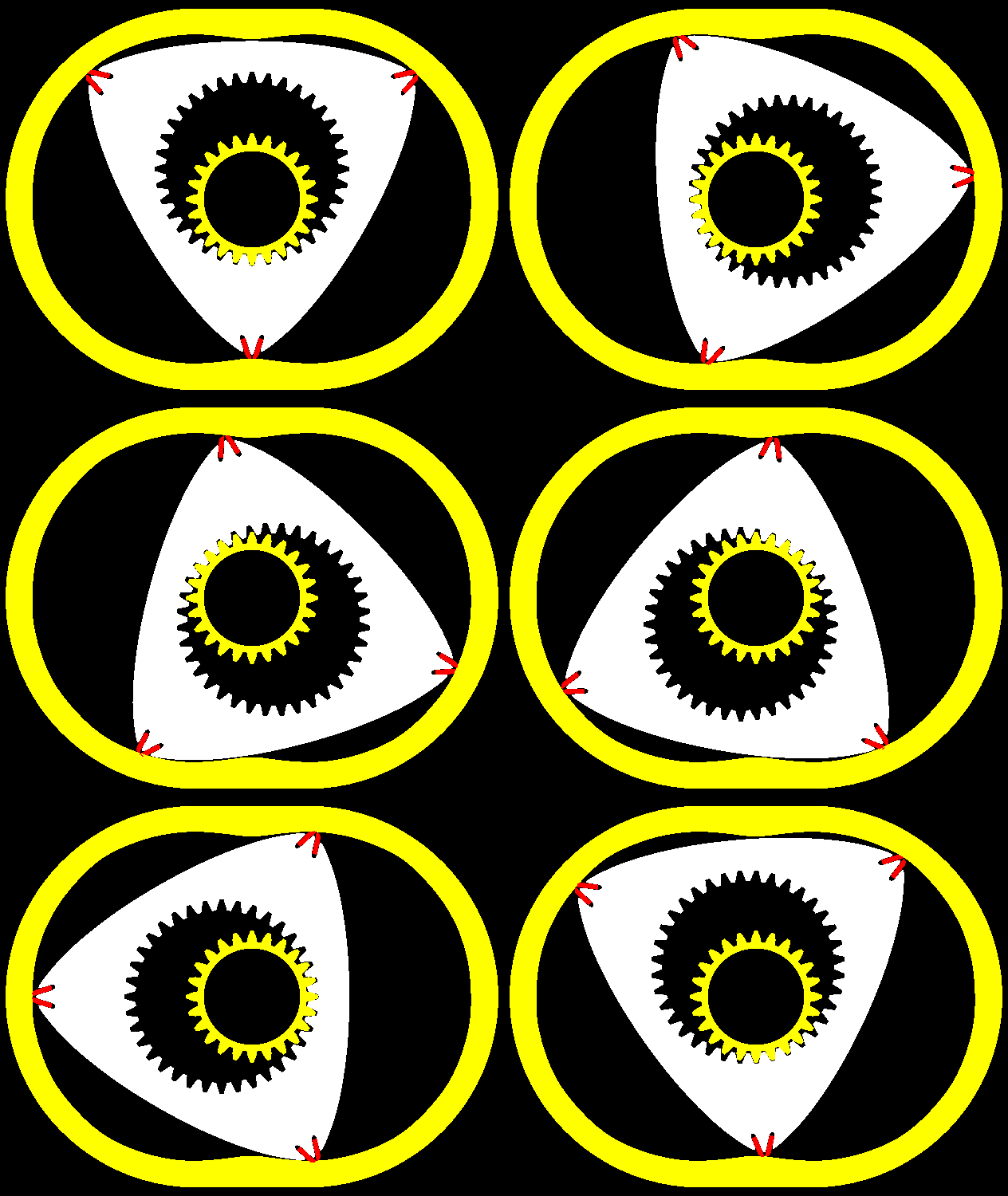
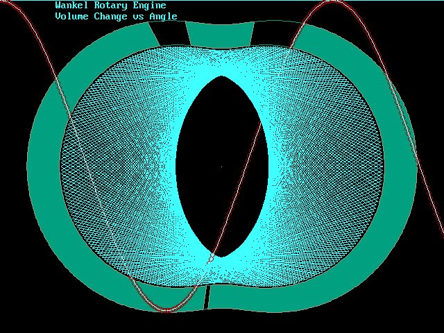
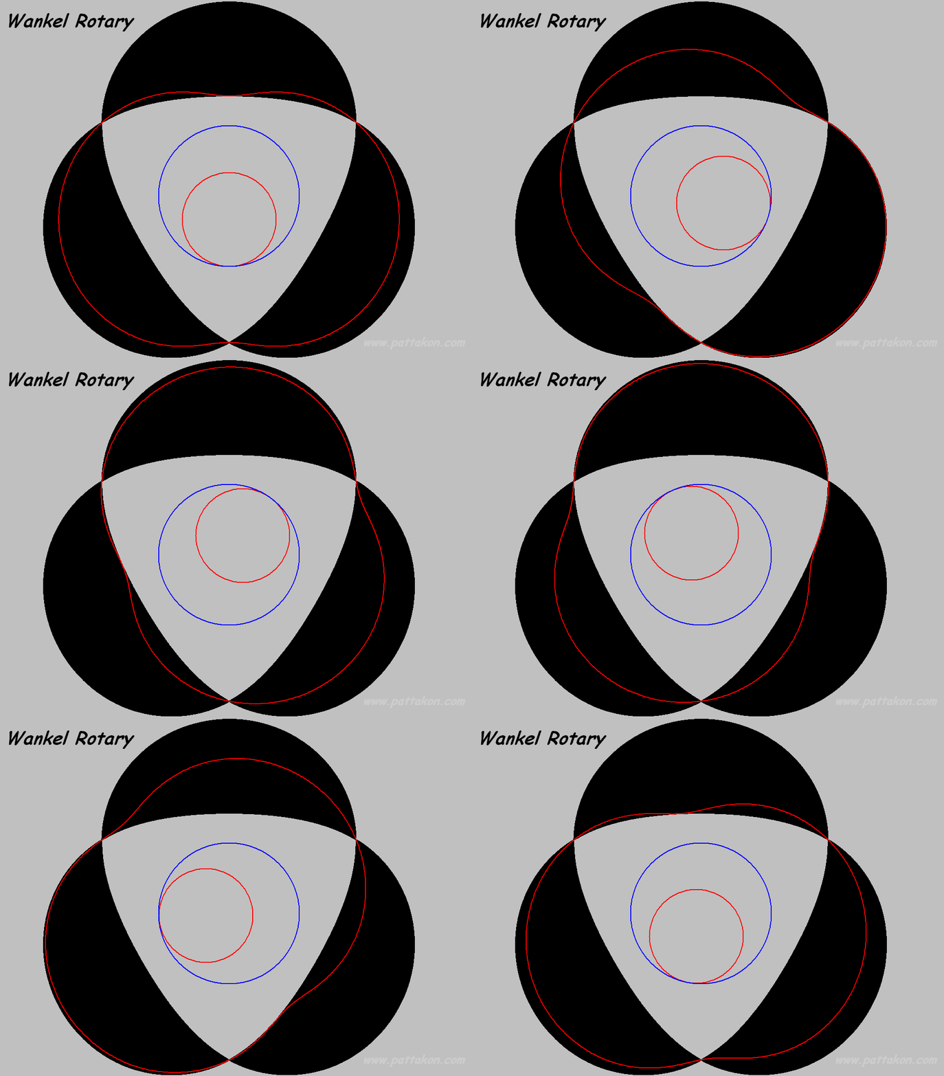
The relation between the volume in a working chamber of the LiquidPiston (say, in their XMv3 model) and the eccentric-shaft angle is pure sinusoidal (which is also the case for the Wankel):

Wankel_Volume_Change.gif


Wankel_L.gif


Based on the above animation, it is easy to understand why, if the Wankel has pure sinusoidal “volume vs angle” relation, the LiquidPiston is also “sinusoidal” as regards its “volume vs power-shaft-angle”.

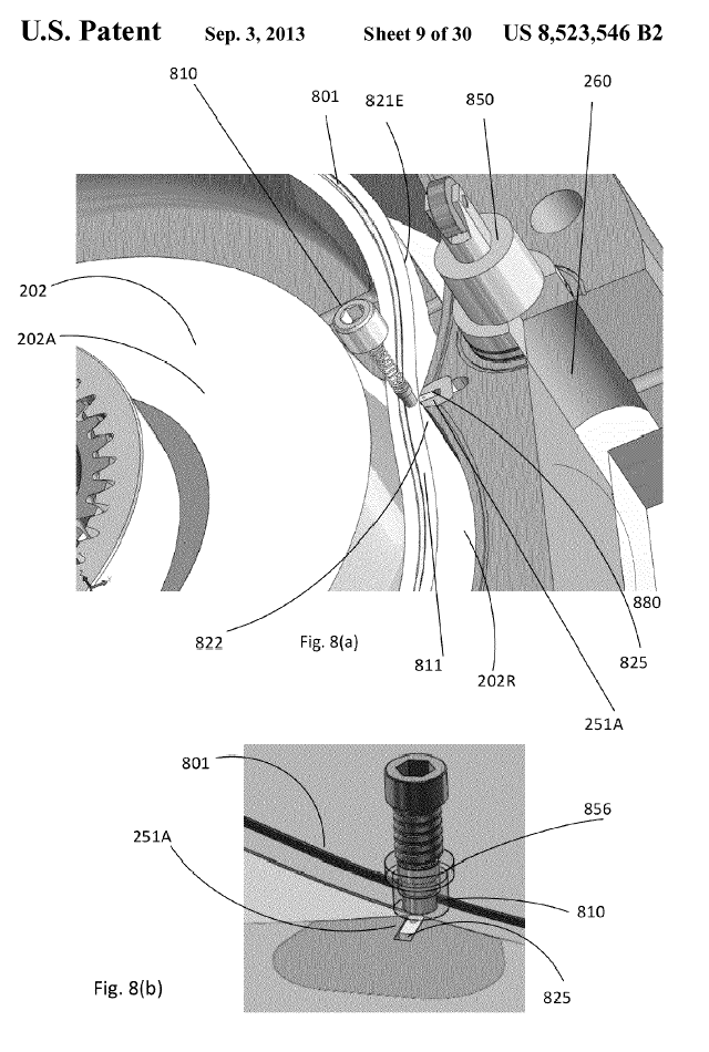
You can’t have a “constant volume combustion” in an XMv3 engine, or, more correctly, in a Colley engine design. Unless you add auxiliary chambers and pistons like the (850) in this patent of LiquidPiston:

LiquidPiston_US.gif


If it is accepted that LiquidPiston rotary engines really run on a “constant volume combustion”, then how can it be called the combustion in a PatOP engine:

PatOP1.gif


PatOP opposed piston engine running on Diesel fuel - YouTube


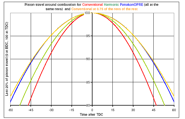
wherein the volume-vs-angle (the blue curve. Following plot) varies, around the combustion dead center, substantially slower than “sinusoidal” (the green curve according which the LiquidPiston runs)?

OPREdwell.gif


We should call it “decreasing volume combustion”?
This is just nonsense.
The thermodynamic cycle LiquidPiston claims (HEHC) is not applicable in their real world engines. Their volume-vs-angle during combustion varies sinusoidally, while there are other engines (like the PatOP and the OPRe and the PatPortLess, see at the www.pattakon.com web site) having a slower “volume-vs-angle” progression around the combustion dead center.

Thanks
Manolis Pattakos
 
Regarding the machining of the working surface shown in the first animation:

On the chock of a lathe it is secured eccentrically a shaft.
The red gearwheel is secured immovable on the lath bed.
The body with its gearwheel (white) is rotatably mounted on the shaft.
As the chock rotates, the body to be machined performs a combined motion (it spins about the shaft and it orbits together with the shaft).
Given the shape of the seals to be used (the simplest form? the circular), the cutting tool has to follow a specific “path” (like half circle, for instance) in order to create / form the working surface on the part (the working surface is whereon the seals will abut and slide during operation; the seals are mounted in grooves made on the outer body).

In case of seals having simple form, even a conventional (not CNC) lathe can be used.

Similarly for the honing / polishing.

The material is to be either spheroidal graphite iron (as in the cylinder liners).


Thoughts? (like: problems you see)

Thanks
Manolis Pattakos

I believe your plan for turning the rotor in a lathe on an eccentric might work, but the problem is going to be the varying angle the cutting tool will be working on the material. In your animation it appears that a single point tool would go from extremes of positive to negative rake. That's going to be difficult to get it to work.

For the rotor to spin the eccentric while meshing with the fixed gear it will need thrust bearings to deal with cutting forces and seals to keep the chips and coolant out of the gears.
 
If the PatWankel works / burns not as the Wankel, but as the LiquidPiston, the combustion will be better than Wankel, the expansion will be “overexpansion”, the cycle will be Atkinson-Miller, the compression will be high and the exhaust gas temperature will be way lower (because the energy of the fuel goes in generating mechanical power and not in heating the exhaust gas).

I'm not seeing it.

In the Atkinson engine the compression and expansion cycles are asymmetric. That is not the case for either the PatWankel rotor or housing, so how is the asymmetry achieved?

In my opinion this motor will never run with the exhaust passing through the rotor.

It is cute that Liquid Piston get DARPA money. Over a decade of funding and still no commercial product.

What material can withstand the heat (and heat differential) of the ported rotor, and yet continue to seal?
 
A practical design can tolerate a clumsy implementation; early Otto engines had total loss lubrication, a candle behind a shutter for ignition, and a petrol-soaked wick for fuel delivery.

And it ran!

Which reminds me of democracy...
 
Hello jCandlish

You write:
“I'm not seeing it.
In the Atkinson engine the compression and expansion cycles are asymmetric. That is not the case for either the PatWankel rotor or housing, so how is the asymmetry achieved?”

When for a modern reciprocating engine it is said it is working on Atkinson-Miller cycle (say, as the engine of Toyota PRIUS) it is meant not asymmetrical motion of the piston, but substantially late intake valve closing (LIVC) that, without significant pumping loss, allows to a part of the working gas to exit from the cylinder before the compression.

Here is an animation of a PatWankel_iGR running according the Atkinson / Miller cycle:

PatWankel_Miller_2.gif


The exhaust opens late (allowing full expansion), the intake closes late allowing to a good part of the entered gas to return back to the “intake manifold”, the compression ratio is high (the compact cavity at the “top” of the combustion chamber is wherein the combustion completes).


You also write:
”What material can withstand the heat (and heat differential) of the ported rotor, and yet continue to seal?”

The apex seals in the Wankel have a much harder life.
And they last, according the Internet, for about 50,000 to 100,000 miles.

The previous animation shows double “apex” (or more correctly “peak”) seals.

Think what they are doing.

A Wankel rotary engine uses two apex seals per working chamber, with the one apex seal (and its groove) shared with the leading working chamber, and with the other apex seal (and its groove) shared with the trailing working chamber.

Each apex seal "plays" inside its groove on the rotor, bouncing between the two flanks of its groove.

For instance, the "leading" apex seal of a chamber, when the exhaust starts in the leading chamber, leaves the "trailing flank" and moves towards the leading flank of its groove, allowing a significant leakage towards the exhaust. At the end of its "stroke" it slaps the "leading flank" of its groove.

There are similar problems in the Reverse_Wankel / LiquidPiston rotary engine: each "peak seal" with its groove is shared between two neighbouring working chambers.


Among the advantages of the PatWankel_iGR design (twin apex / peak seals in different grooves) is the independence of the sealing of neighbouring chambers, also the elimination of the leakage towards the leading and trailing chambers: each seal seats onto the right side of its groove and uses the pressure in its own chamber to tightly abut on the working surface during the high pressure period of the cycle, i.e. as in the reciprocating piston engines.

Significant advantage is also that only the one face of each seal relates with high temperature gas; its other face abuts on the cool "bottom" of its groove; this way, the thermal load on the seal reduces substantially (the number of combustions it participates is half of those of a conventional apex seal), the mechanical stress of the seal is reduced substantially (there is neither bouncing of the seal among the flanks of the groove, nor slapping of the seal on the flanks of the groove when the one of the neighbouring chambers fires), the cooling of the seal is improved, etc.
All these improve the long-term reliability of the engine.

According the previous, the apex seals (or the peak seals) of a PatWankel_iGR can last several times longer than the apex seals of a Wankel.

Thanks
Manolis Pattakos
 
Hello Garwood

You write:
“For the rotor to spin the eccentric while meshing with the fixed gear it will need thrust bearings to deal with cutting forces and seals to keep the chips and coolant out of the gears.”

You are right.
They are required thrust bearing to keep axially the body.
It is also required a “casing” to keep clear / oiled the gearwheels.


You also write:
“I believe your plan for turning the rotor in a lathe on an eccentric might work, but the problem is going to be the varying angle the cutting tool will be working on the material. In your animation it appears that a single point tool would go from extremes of positive to negative rake. That's going to be difficult to get it to work.”

The red semi-circular thing shown in the animation is actually the seal (a part of it) that will run on the surface of the inner body.

I was thinking of using two tools. One for cutting the “left” half of the working surface (including the left-flat-side working surface), and one for the right half.

In case of a conventional lathe, I was thinking of a rotatable support (say like “U”) for the cutting tool. If the axis of rotation of the cutting tool is on the center of the red seal (shown in the animation), with one tool it can be cut the complete working surface, with the tool being permanently correctly oriented.
It sounds not “too professional”, however the final product could be better.

Thanks
Manolis Pattakos
 
Manolis, you'll double the Greek national debt with that wire edm work for the seals ;-) I was thinking waterjet with a cnc grind or milling second op.

While your lathe idea for the rotor would probably work , finding a machine shop willing to do it might prove difficult . For most shops this would be a step into the unknown (Samy's nightmare) .

Making a prototype using 5axis cnc may be a better approach. Surface finishing could be problematic!

Have you an idea of the size of your prototype? (LP prototype was perhaps 200-300mm diameter)

Bill
 
Hello Limy Sami.

You write (about the machining of the inner body):
“It's a total nightmare”

Can you please be more specific?

Why it seems to you a “total nightmare”?

What I see is a simple machining work wherein the piece is “located” on the lathe one time only, and is finished without removing it.

Suppose the piece is mold, made of spheroid graphite iron, with the inner passageways and with the ports formed at molding.

You put the part the way described on a CNC lathe.
You program the motion of the cutting tool (this motion actually replicates the form of the seal to be used).
And you cut / polish the piece.

It follows a dynamic balancing of the part (there is plenty of material from inside the body to be removed).

And the inner body (i.e. the basic part of the engine) is ready to operate.

What is left?
The seals (they can be cut accurately from a steel sheet with a wire-EDM machine).
And the external body which needs accurate machining only in the grooves for the seals.

And what you have is a complete engine with five working chambers (its vibration-free-quality and smoothness compare only with the best reciprocating piston engines, like the V-8, the V-12 and the similar).


Think: in total there are: an inner body (on the external surface of which they run the seals), an outer body (comprising the grooves of the seals) and a set of seals.


Compare this “nightmare” with the machining required to make a four-in-line-16valve reciprocating piston engine.

Thanks
Manolis Pattakos

I take my hat off to you sir, ........you are obviously 10,000 times the machinist I will ever be.
 
Another thought : could you finish a cnc milled rotor with a Sparker?

If the rotor were small enough to fit the baths, (~300mm dia) one of our ingersol spark eroders could probably track the surface.

Manolis, what surface finish does it require? If you're proposing steel seal I guess the rotor is hard chrome (iron? ).

Bill


Back
Top