BigToys
Aluminum
- Joined
- Feb 14, 2006
- Location
- New Jersey
A couple of years ago I was at one of my favorite machinery dealers and they were throwing away a couple of Mitutoyo GML 3705 Digital Readout systems that came off of some old Bridgeport mills. Both were "dead", meaning that when you turned them on, the displays remained off. I later bought a couple more Mitutoyo DRO boxes that were also "dead" with the hopes that between four units, I could salvage at least one DRO box.
Working with an electronic engineer friend, we found the cause of the problem which all 4 DRO boxes had, and were able to fix them. In brief, a couple of capacitors on the circuit boards wear out and cause a short circuit, which in turn, causes a thermal cutoff in the transformer to overheat and open, disabling the power supply. Since all four units had the exact same problem, there's probably others out there that also have this issue. Below are the details of the repair.
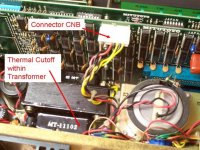
To confirm that the power supply is broken, check the power on connector CNB, the white one in the center of board COUNT2. It has both DC to supply the logic and AC to run the displays. The pin/wire colors are 1= Brown, 2= Black, 5= Red, 6= Black, 7= Yellow and 8= Black. When working correctly, the voltages should be - across pins 1-2 is 35 VDC, 5-6 is 5.5 VDC, 7-8 and 8-9 is 12 VAC, 7-9 is 24 VDC with pin 8 bias to +5.5 VDC.
In my experience, no power on the CNB connector means the thermal cutoff fuse located WITHIN the transformer itself, hidden out of sight, is burnt out. The primary transformer winding is thus an open circuit. This can be verified by measuring the resistance between the common black primary winding lead (black) and the 120VAC tap (orange). By working carefully with patience, it's possible to open the metal casing of the transformer and replace the 126 deg. C thermal cutoff. It is connected to the black primary lead and located under a couple layers of insulating paper. I used a Radio Shack replacement, Thermal Fuse 270-1322 rated at 264 Deg F, 129 Deg C, and used some glass cloth tape for additional insulation.
To check for shorts on the circuit boards, remove connector CNB and measure with an ohmmeter between pins 1-2 on the (attached) pair of circuit boards. With working boards, you get 600 ohms; with the probes reversed you get 6000 ohms. As was the case with all four of my units, there was 0 ohms, indicating a dead short in one or both of the circuit boards.
Each of the circuit boards has a 10uF, 35V tantalum capacitor across the 35 VDC rail (C12 on board COUNT1 and C72 on board COUNT2). Unfortunately, when these capacitors fail, they short. Both capacitors were shorted, so I replaced them with tantalum 10uF, 50V caps, which have a higher voltage rating and hopefully will not break down in the future.
So that's the story, a few hours of labor, a few bucks in parts, and a few old workhorses have come back to life.
Working with an electronic engineer friend, we found the cause of the problem which all 4 DRO boxes had, and were able to fix them. In brief, a couple of capacitors on the circuit boards wear out and cause a short circuit, which in turn, causes a thermal cutoff in the transformer to overheat and open, disabling the power supply. Since all four units had the exact same problem, there's probably others out there that also have this issue. Below are the details of the repair.
To confirm that the power supply is broken, check the power on connector CNB, the white one in the center of board COUNT2. It has both DC to supply the logic and AC to run the displays. The pin/wire colors are 1= Brown, 2= Black, 5= Red, 6= Black, 7= Yellow and 8= Black. When working correctly, the voltages should be - across pins 1-2 is 35 VDC, 5-6 is 5.5 VDC, 7-8 and 8-9 is 12 VAC, 7-9 is 24 VDC with pin 8 bias to +5.5 VDC.
In my experience, no power on the CNB connector means the thermal cutoff fuse located WITHIN the transformer itself, hidden out of sight, is burnt out. The primary transformer winding is thus an open circuit. This can be verified by measuring the resistance between the common black primary winding lead (black) and the 120VAC tap (orange). By working carefully with patience, it's possible to open the metal casing of the transformer and replace the 126 deg. C thermal cutoff. It is connected to the black primary lead and located under a couple layers of insulating paper. I used a Radio Shack replacement, Thermal Fuse 270-1322 rated at 264 Deg F, 129 Deg C, and used some glass cloth tape for additional insulation.
To check for shorts on the circuit boards, remove connector CNB and measure with an ohmmeter between pins 1-2 on the (attached) pair of circuit boards. With working boards, you get 600 ohms; with the probes reversed you get 6000 ohms. As was the case with all four of my units, there was 0 ohms, indicating a dead short in one or both of the circuit boards.
Each of the circuit boards has a 10uF, 35V tantalum capacitor across the 35 VDC rail (C12 on board COUNT1 and C72 on board COUNT2). Unfortunately, when these capacitors fail, they short. Both capacitors were shorted, so I replaced them with tantalum 10uF, 50V caps, which have a higher voltage rating and hopefully will not break down in the future.
So that's the story, a few hours of labor, a few bucks in parts, and a few old workhorses have come back to life.