What's new
What's new

Moore No. 3 Micro-Sine Table

RJ Wels

Plastic
Joined
Apr 19, 2020
Hi,

I thought I start my first post with three scanned items, Moore Sine Table (data sheet, instructions, tables).

Data sheet
Moore No. 3 Micro-Sine Table, Data Sheet.pdf - Google Drive

Instructions
Moore No. 3 Micro-Sine Table, Instructions.pdf - Google Drive

Book of Tables
Moore No. 3 Micro-Sine, Book of Tables.pdf - Google Drive

Note:
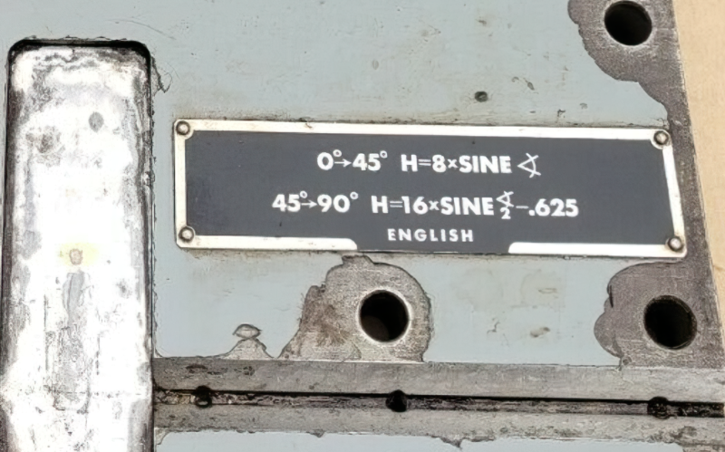
As a point out, in the Book of Tables, there are differences between the printed height setting (H) vs. those you would calculate using the formula.

Among the largest of these differences, I found 10 that range from 0.20 to 0.29 arcseconds and in particular, one at (37 Deg. 35 Min.) with a difference of 1.8446 arcseconds.

Interestingly in the book it does say, "Moore cannot guarantee that these tables are error-free".

Welcome any comments.
 
That is an interesting sine table. And the equation takes a little bit of thinking to see how it works.

It has an advantage over the more traditional sine table/bar in that it has good accuracy at all angles from 0 to 90 degrees. Another advantage, if you can call it that, is that it is mentally easier to scale to different sizes. Traditional sine bars are either 5" or 10" sizes because with the 10" size you can use any sine table and just multiply the sine value there by 10 (move the decimal point over one place) to get the size of the stack of blocks. And for a 5" sine bar, you do the above and then divide by 2. Either of these can be done easily and quickly on the shop floor. But very few traditional sine bars are made to other sizes because the math gets a bit more complicated. Often other sizes would be a better fit the work being done. And metric sizes really leave you in a pickle. 100 mm would mean multiplying the sine value by 100 and that is easily doable. But 100mm is only around 4" and that is a real short size so accuracy suffers. So, 200 mm and you need to multiply by 100 and then by 2. That gives you a usable size, with good accuracy and fairly easy math.

But with this Moore design the math is already more complicated so there is no reason not to make a size you really want, like the 8". And it is accurate over the full 0 to 90 degrees.

That equation and/or the need for a table that is specific to this model of sine table is the greatest drawback I can see.

It is interesting and I would love to have one.

PS: The formula is there on the cover of their Book of Tables and it can be used in a program like Excel to develop your own table of settings. That should get around any question about the accuracy of their tables. And I can vouch for the accuracy of that formula. But I would not reproduce the entire table in Excel. I would just create a calculator sheet where you can enter any angle and, using the formula, it spits out the length needed.
 
So, Foundations of Mechanical Accuracy was written by Wayne R Moore (I was reading it when I saw this post) and the posted article is about Richard "Dick" Moore. I assume these are are the same guy? What gives?

EDIT: Never mind. I just found that Wayne is Dick's son.
 
I'm have trouble visualizing exactly how gauge blocks are used to set the angle on a Moore Micro Sine table no. 2 (meant for use with the 11" rotary table) ... any links to instructions for this ?
 
I'm have trouble visualizing exactly how gauge blocks are used to set the angle on a Moore Micro Sine table no. 2 (meant for use with the 11" rotary table) ... any links to instructions for this ?

I could find no instruction manual. But deduction from pictures (ie ebay, books).

The height (H) formula to use with the gage block(s) is printed on the bottom plate (in between the table).

For angles 0 (zero) to 45 degrees,
- slip the gage block(s) between the plates (lapped center of bottom plate and top gaging pin).
- Note, zero degrees requires no gage block

For angles 45 to 90 degrees,
- install (screw in) the additional gaging pin
- set the adjustable gage block assembly to calculated height (H)
- place the assembly between the top and bottom gaging pins
- Note, if you don't have the assembly, then you can wring together gage blocks.

The simplest angle to verify is 30 degrees which can be obtained with a 4 inch gage block.

Hope that helps.
 
I think this is a no. 2, but I can't be certain:

172226563.png
 
Last edited:
Hi,
<snipped>
Among the largest of these differences, I found 10 that range from 0.20 to 0.29 arcseconds and in particular, one at (37 Deg. 35 Min.) with a difference of 1.8446 arcseconds.
<snipped>

I tried 37[SUP]o[/SUP] 35' and got the same as you: +00[SUP]o [/SUP]00' 01.84455787" error.

The stack height listed is: 5.58207"

It should be: 5.58200404" rounded off to fit their format.

That is still close enough that no one on the shop floor ever noticed, most likely, though I bet the error would have embarrassed some people at Moore. Good eye!

I wonder if they used a store-bought sine chart or if they used something like the Taylor series (or a variant that converges more quickly) when calculating their table?
 
Last edited:
This is my initial understanding of the no. 2 (I have very little to work from):

Don't use the Book of Tables in post #1. That is for a no. 3.

0 to 45 degrees:

Sine (angle) * 8

172227523.png


45 to 90 degrees:

(Sine (angle / 2) * 16) - 0.625

172227522.png


172227521.png
 
Last edited:
I noticed something about the change between the Moore No. 2 Micro-Sine Table and the No. 3 model.

They went from two methods to one when calculating the gage block's height and how the block stack is used.

What I find interesting is the gage pin's diameter changed from 0.625 to 0.6161. Why would they do that? I think I see.

First, they chose a 0.5000 gage block to correspond with zero degrees. When they calculated the angle using the chosen block it resulted in the odd angle shown below:
172230561.png


To remove the decimal part of the angle's number, they changed the diameter of the gage pins:
172230562.png

That allowed them to use 8 in the formula instead of 8.0639

172230576.png


I'm just speculating...
 
I tried 37[SUP]o[/SUP] 35' and got the same as you: +00[SUP]o [/SUP]00' 01.84455787" error.

The stack height listed is: 5.58207"

It should be: 5.58200404" rounded off to fit their format.

That is still close enough that no one on the shop floor ever noticed, most likely, though I bet the error would have embarrassed some people at Moore. Good eye!

I wonder if they used a store-bought sine chart or if they used something like the Taylor series (or a variant that converges more quickly) when calculating their table?


Regards to 37 Deg 35 Min
It appears the H(in.) 5.58207 print in the book was a typo. Convert the H(mm) print metric "141,783" to inch equivalent = 5.582008

Instead of typing in 5.582008 they typed in 5.58207 missing a zero, it seems.

These calculations were performed in the 80's. The "computers" executing the Sine() function most likely used the CORDIC algorithm.

Correction, the calculations were performed in the late 60's since their book "Foundations of Mechanical Accuracy" was first published in 1970 (describing the No. 3 Micro-Sine Table). The earlier date, suggests it's even more likely the CORDIC algorithm was used for the trigonometry functions.
 
I noticed something about the change between the Moore No. 2 Micro-Sine Table and the No. 3 model.

They went from two methods to one when calculating the gage block's height and how the block stack is used.

What I find interesting is the gage pin's diameter changed from 0.625 to 0.6161. Why would they do that? I think I see.

First, they chose a 0.5000 gage block to correspond with zero degrees. When they calculated the angle using the chosen block it resulted in the odd angle shown below:
172230561.png


To remove the decimal part of the angle's number, they changed the diameter of the gage pins:
172230562.png

That allowed them to use 8 in the formula instead of 8.0639

172230576.png


I'm just speculating...

Great illustration. If I may add..

The design was based on the "double-sine" principle, using two points of reference on the plate to establish the "correct" angle. The gage pin holes were "located" on each plate using their "special 4-spindle machine". There is a picture of the machine in their book (Foundations of Mechanical Accuracy).

From deduction. The operator had to machine a total of 8 holes (4 axis-of-rotation and 4 gage pin). One gage pin and one axis hole on each side of the plate 8” apart (between centers) with the gage pin center at a -4 degree offset from plate surface parallel. Holes on each side of the plate were aligned parallel at exacting heights from the surface so a 0.500 gage block between gaging pins can set the 0.00 (zero) degree angle. The hand scraping most likely completed before machining.


Back
Top