What's new
What's new

Need advice on making a progressive punch

KIMFAB

Stainless
Joined
Jun 21, 2008
Location
Logandale,Nv
I do a lot of punched parts out of 6061 T6 aluminum but I usually have my dies made. I'm a fabricator not a machinist.

I have a need to punch a lot of parts for a new product. I figured I might as well try to make the die myself since it is a simple part.

Here is the drawing I made using Autocad along with a sample part.

diea042.jpg


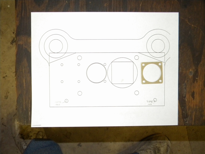
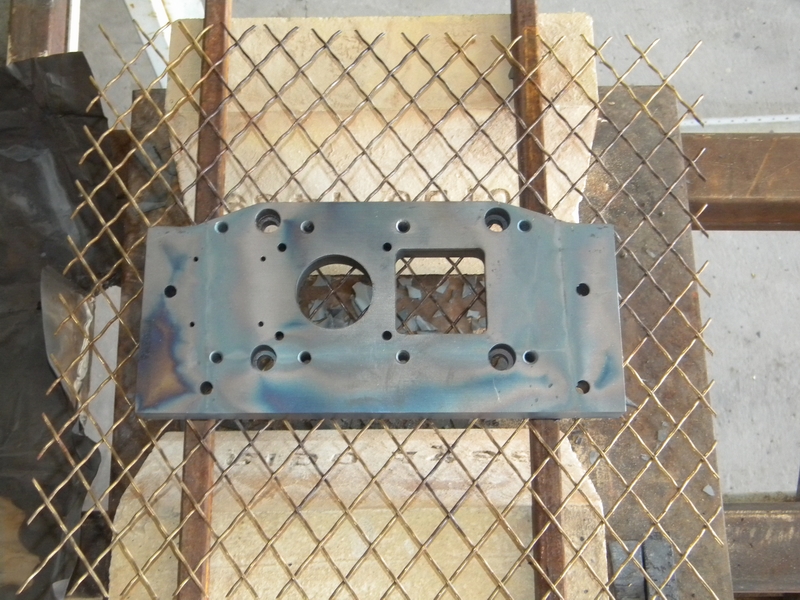
I will be making a progressive die where the first stage makes the 4 holes, the next stage indexes and cuts the center hole and the last stage blanks out the finished part.

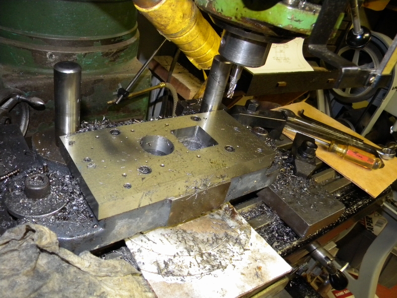
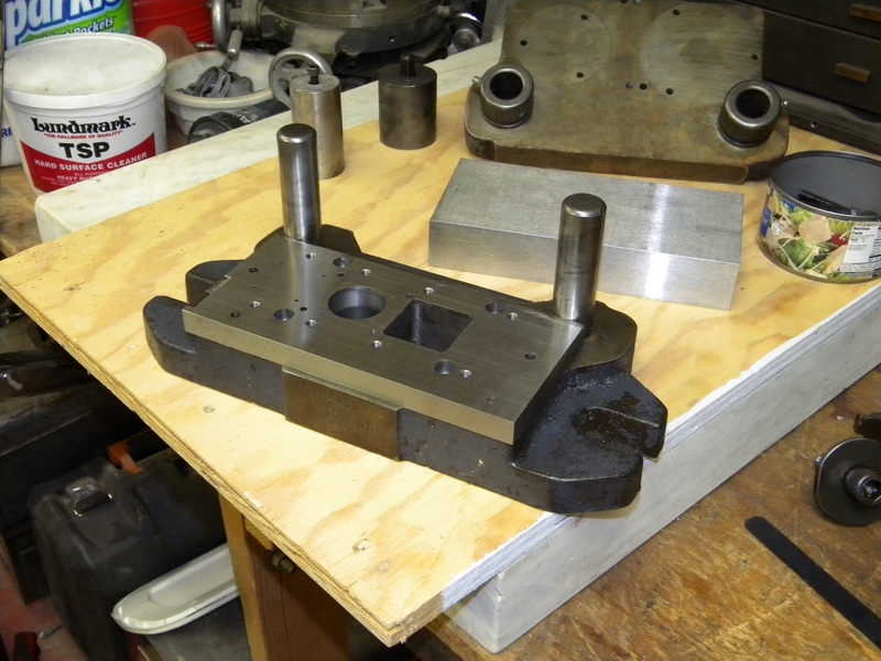
The pin in the lower right is a 1/4" alignment pin left over from the die sets last use.

diea036.jpg


I managed to measure it correctly and make the hole so now it engages properly with the 3/4" piece of A-2 that I'll use for the plate.

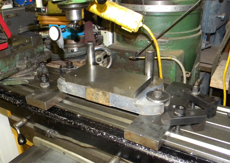
The A-2 plate is aligned with the 2 large pins of the die so that the front of the A-2 is parallel with the pins and 4 1/2" from the center of the pins and the left side is perpendicular and aligned with the outside of the left pin.

I understand that A-2 expands a bit when heat treated so the left alignment pin will be placed after treating.

diea039.jpg


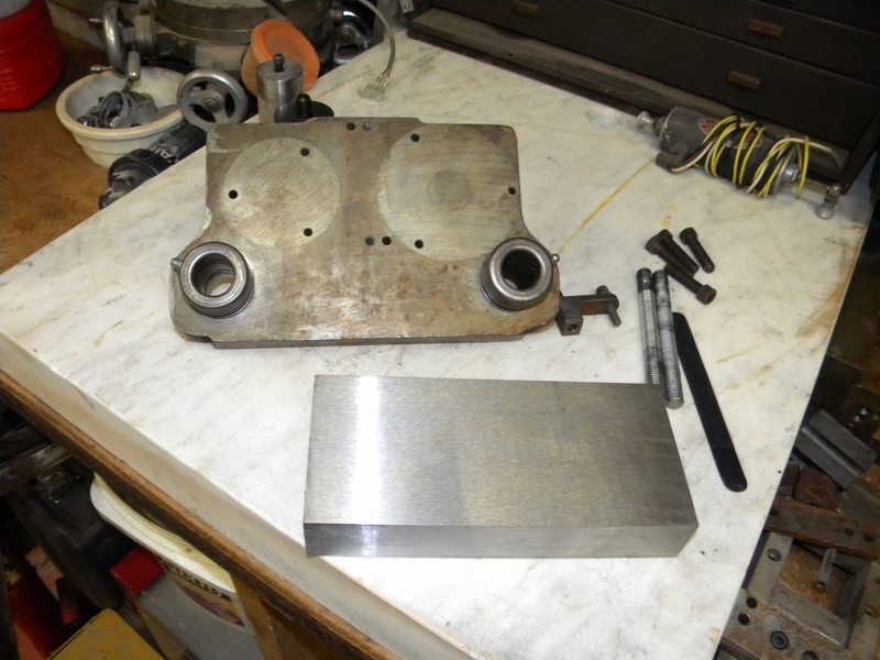
What I'm trying to figure out is how to align the top plate with the top of the die so when the die is assembled the whole thing matches up.
The guides on the top of the die are not round on the outside and I don't think I can index on them.

Could someone tell me how the big boys do it?
 
Last edited:
Use DP's to locate the plate to the bottom of the shoe, BUT also use DP's to locate the plate to the top part of the shoe. Those will be reference holes , that you can pick up when you start locating the punches. The extra top DP holes will be empty when the die is finished. Just keep a sketch of all the locations when you drill/bore/ream.
 
Of course! What is an obvious answer to someone who knows what he's doing had puzzled me for days. Thanks

Maybe I'll change the title to "How a hack makes a die":D
 
What we used to do:
1. remove the bushings from the upper shoe and put them in the top of the upper shoe.
2. Assemble the die set. This will place the upper and lower shoe together.
3. Drill all of the tapped holes, and drill & ream all of the dowel holes through.
4. Remove the bushings and install on bottom of top shoe.

For most punch press work, this will get you close enough to get started. You should be close enough to locate the punch pads with screws and then do a hand allignment before doweling.
JR
 
Yes, I plan on using a stripper plate.

I had thought of putting the bushings on the top but with the short posts and a 1 1/2 "holding plate I didn't think they would engage properly.

I'll probably have to replace the posts anyway because they are too short (2" throw on the press) so this method could work.

Thanks for the help so far. I just may be able to pull this off.
 
Kimfab - You are missing a few things. How thick is your materia (needed to calculate the die clearance)? Relief angle in die block? How are you controlling the progression? Stripper as mentioned before. Guide rails? My advise: At a min. get yourselves a good die book and do some reading or have a die maker show you what is needed.
The mounting itself is not very hard to do but the punch holder with the punches must be correct as far as the spacing goes and must be the same as the die block. This is very important especially if you are cutting thin material and have a line to line condition. Your posts at min. shut high should be about 1/2 " below the top of the die.
 
I probably should clarify myself here. First off, I'm punching .063 material which according to Dayton Progress would require a .003 clearance all around.

Here is a picture of my setup. I am using a guide plate and if you look at the drawing in the first post you will see 2 holes next to the circle in the middle for indexing.
The stripper will be a piece of 5/32 plate with an .080" groove for the material.

diea003.jpg


My machinist neighbor got me into this mess several years ago when he built me this punch which has so far put out in excess of 100,000 parts.
Unfortunately he retired and spends his time golfing and driving his fancy bus everywhere so I have to fend for myself.

The more discerning observer will also note that the die is backwards. This was necessary because I did not have room for it on my old press.

diea004.jpg


This old girl gave me about 5000 parts between repairs which had to be made because parts are unobtainable.

As far as relief angle I think what you are talking about is the relief under the holes in the die. I plan to have that about .1" down from the top the hole will be probably .01" larger.

I share your concern about the post height. I had to change posts on the original die because they were too short.

Thanks for all the suggestions so far. It's good to have knowledgeable participation on a first attempt.
 
The punches will be held in that piece of lo carbon shown in the third pic of entry 1.
Anybody see anything else I may be missing? Thanks
 
Well here's where I'm at.

diea009.jpg


Got all the holes located and the 2 large holes done.
The bad news:
Didn't allow enough for tool springback when boring the round hole and it is at + .010 instead of + .006-7
Started the last run on the hole off centered and dug in about .030 before it was stopped. I'll have to scrap the part or take about .030 off the top if I decide to run with the larger clearance.

On the other hand the square hole came out looking pretty nice. I'm happy with it.

What was that saying "make 2 and throw the first one away?"
 
I would use off the shelf buttons (if available in your size) than you can make inserts for the big round and square holes. For longevity use ejector punches.(you might have to build your own for the big holes)

Note : the material shears at aprox. 2/3 of the way through

Get the holes wire burnt after hardening.
 
Heavey
You caught me on the "getting the holes wire burnt."
Are you speaking of EDM or some hardening process?

Also, on ejector punches, my dies have always been plain with the die holding the last 3 slugs and dropping the rest as they were punched.
Only problem I've had was when I had a load of soft metal they would sometimes stick.

Gotta go party now. Something about a 40 year wedding anniversary today.
 
I haven't done this for years, but I'd think that the last station would wrinkle the part when doing the blanking. You might need a sprung pressure pad in the bottom shoe to support the part and than eject the part with an air shot blowing across the face of the die.

Other than that, Good thinking on the die design.

Frank
 
Ejector punches are punches equipped with what is commonly called an oil pin. The spring loaded pin protruding from the bottom of a punch will keep the slug (or part) in the die cavity. Otherwise oil and suction could make the slug stick to the punch and on the next hit - crash. A pressure pad in the die portion is not recommended because it will push the slug back into the strip. When you talk about an air blast you are most likely talking about a compound die - like a washer die. But in a compound die you have a shedder in the top punch also equipped with an oil pin. When the shedder pushes the part out the oil pin will push it off the shedder and an air blast can than blow the part into a container set in the back of an OBI.

Ps.: If you are thinking about having your die cavities wire cut after heat treating - make sure you include a double min. draw for your type of steel immediately after cutting or your die block could crack where ever there is a sharp corner. Juergen
 
Okay, I know I'm late to the party ...

(Wall O' Text mode activated)

As often as possible, this is how we do it around here.

It all starts at the design stage.

The part prints for our die/punch plates are dimensioned from one of the posts/bushings.

Make sure it's the same post/bushing for both plates.

On four-post sets, don't use the offset post/bushing.

The die block gets through holes, the die plate gets tapped.

The punch plate gets through holes, the punch holder gets tapped.

To machine the plates:

Mount the die plate, indicate the pins/bushings true and clamp it down.

Use an indicator to center on your origin pin/bushing and set X/Y zero.

Machine all your tapped, dowel, and slug holes.

Now, mount your punch plate to your die plate.

Using 1-2-3 blocks or similar to support it and keep it parallel, clamp it down.

This way you use the same X/Y zero and know your holes are exactly where they should be in relation to your die plate.

Now, machine all your through holes for your bolts, c'bores will be on top, but DO NOT machine your dowel holes.

When this is done, remove the die set to your work bench.

Mount the die block to the die plate.

Using spider shims (you may have to make your own) align the punch holder/punch combination to your die block.

Now mount the punch plate and carefully clamp the punch holder/punch combination to it, then bolt them together.

Remove the combined plate/holder/punch.

Use drill bushings in the punch holder's dowel holes to get them started on location and then drill and ream them to size through the punch holder.

Now everything should be where it belongs and your clearance should be, and remain, the same on all sides.

If you've managed to read this far, I hope it was some help.

Edit:

We wire-edm (burn) all of our die blocks, strippers, punch holders, and most of our punches so little to no work gets done to them in the mill at this stage.
 
Last edited:
Here's where I'm at right now.

diea024.jpg


This is too much work for an old man! I appreciate the helpful comments. Keep 'em coming! Glad to see the wire burn thing cleared up.

Took a little off the top and I'll try to save this unit. If you look at the upper right you'll see some scratch marks that were left from topping it.
I'll have to cut the upper corners off also for clearance.

I think it's just about ready to pop in the oven. Looks like we need about 1700 degrees. I have only hardened the O-1 stuff so I have more questions.

It looks like this wants to be wrapped in foil, so the question is; leave the foil on or take it off to cool? Is it OK to lay it across a couple of firebrick for cooling or does it need to be supported so it doesn't sag?

So far I'm happy with the results, and it is a good thing I have plenty of time because now I need a rest. Fortunately the wife has planned a 2 week vacation for 4 - Me and 3 women driving to Seattle to go on an Alaskan cruise. :D

I read somewhere that A-2 should be tempered right away so I'm starting early tomorrow.
 
Last edited:
leave the foil on or take it off to cool? Is it OK to lay it across a couple of firebrick for cooling or does it need to be supported so it doesn't sag?
You can leave the foil on all the way through tempering if convenient. You can take it off as once the surface temperature goes below about 1200F. I usually leave it on.

Ideally, use a rack that gives good support and allows convection airflow. You might find a cheap kitchen roasting rack strong enough sacrifice for the purpose. Beside the saggy thing, the firebricks will probably have a noticeable impact on cooling where they are in contact.
 
I couldn't wait and took the foil off as soon as I could handle the piece.
I heated it to 1500 and let it soak for a half hour and took it to 1750 and let it soak for another half hour and pulled it out.

diea048.jpg


I'm waiting for the oven to get down to 400 so I can temper it.
I'll probably let it soak for about 3 hours.

Probably could just lay it in the sun as hot as it is here. :D
 
Missing?

A ways up you asked what was missing.

A way to index the stock accurately? We often have a cutter that notches the edge of the stock and then that pushes against a stop. I'd have to do some head scratching for three stations.

More details to the drawing? I generally run out of space for springs and stripper bolts and all the other geehaws (like notchers and stops mentioned above) even when I do a very careful detail layout its a very tight squeeze.


Back
Top