What's new
What's new

O.T.~ Trouble removing hydraulic pump from engine

JoeE.

Titanium
Joined
Aug 31, 2006
Location
Kansas
I mentioned a few weeks ago about getting this little V.M. Motori Detroit / Sun model 2105E1 air cooled 2 cylinder diesel. Made in Italy, the company was absorbed by Detroit years ago, then spun off for some reason.

Anyhow...this engine drives a vane pump. I've drained the hydraulic system, so there is no oil available to the pump. I want to remove the pump so I can get the engine running, not wanting to power the pump dry.

That would be detrimental to the pump, wouldn't it?

Anyhow, I figured that I would unbolt the pump and pull it and the coupling half out and set it aside.

Well, that didn't happen.

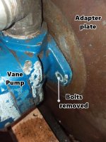
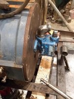
Pump will not come away from that adapter plate one iota.

Removed all the bolts holding the adapter plate to the bell housing, and that plate won't back away more than a few thousandths. It won't rotate, either. I looked real close and didn't find any holes that may contain a locating pin or dowel. The plate won't wiggle or twist or anything... .like there may be some protrusions on the inside of the plate to locate it in relation to the flywheel or whatever's inside that bell housing.

Unbolted, the pump will freely rotate around it's axis, but won't slide back ANY!

Anyhow, I'm stumped. I've tried driving the plate back with the edge of a chisel hitting on the edge of the plate. I've tried pulling on the pump with my hand while I tap the sides of the pump with a ball pein.

Unless the pump shaft and it's coupling are just a real tight tolerance.. I can't imagine why I can't jar it loose. Nothing's giving..

I took some pics and put info on them to show what I'm talking about.
3.jpg

2.jpg

1.jpg
 
Nothing seems amiss on external examination.

"Internal derangement"?

After unbolting pump from adapter plate, pump body rotates freely.
 
JHOLLAND1's option.

If JHOLLAND1's doesnt help the adaptor plate may have a shoulder on the back side that's just tight around the rim in the bell housing. You could try some heat around the rim of the bell housing to expand and gain some clearance. It may not take much.
Moving quickly enough not to allow too much heat to sink into the adaptor plate.
It seems the pump should slide out of a coupler. But its not. Usually has a splined or keyed or cogged coupler.
There isn't a small access port anywhere to loosen set screws on the coupler on the shaft
 
Joe,

Looking at one of the pictures of the large adapter plate it appears there are some threaded holes that are not meant to attach the plate but to back it off..much like an electric motor on a C-face reducer. My guess is there is some type of coupling inside the machine that has worn and notched a bit which is preventing the pump and adapter from coming off. I don't think there is anything holding it as there is no real means to access that area.

Hold you mouth right, out think the thing and I'm sure you'll prevail.:)

Stuart
 
Joe, what is the model code on the back of the pump. It may be a spline shaft that is worn and sets up a strange wear pattern to lock the spline. I’ve seen this a few times where you have to disassemble the pump from the back side and it will uncover a spiral ring holding the main front bearing. From there you can slide off the front cover assy to expose the bare shaft. Exposing the shaft will allow you to get some penetrating oil and reverse torque to hopefully free it up. The shaft more than likely is toast anyway but those are easy to get a replacement.
This all assuming it has a spline shaft.
 
In that type of Vickers pump,its not uncommon for severe spline fretting to occur,and a large buildup of congealed red goo to clog the end of the spline....In fact one common failure is spline disappearance.....Any way ,to get the pump apart ,the vane rotor is a loose splined fit on the shaft,the shaft is pressed thru a ball bearing,and retained on the inside by a circlip,and the bearing retained in the housing by a circlip on the OD.
 
My guess is the splined shaft extends through the drive splines. The hammering has worn into the pump shaft, allowing it to turn and locking it in place on the drive. I'd burn a hole in the mounting plate to see what is in there. If necessary, I'd burn a hole around the pump to allow the outside of the drive plate to be removed over the oil pump. The mounting plate is the least fussy and easiest repaired/replaced part.
 
Sorry for no updates... got busy and forgot I'd posted this. Been working 12 hour days and no time to visit shop.

With nothing to lose, I'll take the pump apart and go at it that way.
 
Ok.... I disassembled and removed 2/3rds of the pump body. There is nothing to indicate that the shaft is held tight to the coupling by anything that was internal to the pump.

I managed to drive some wedges in and get the mounting plate away from the bell housing about a ¼".

I can see down in there with the aid of a light.. and the pump shaft IS going in to a coupling-half.

When I do that, the pump body is drawn tight to the mounting plate and will not rotate as before. Something is holding the coupling captive, but it seems to be flexible enough to let this pulling force withdraw it from it's grip just a bit. I didn't push it by trying bigger wedges (screwdrivers) to see if it would finally pop loose from it's grip.


I can't see the whole half, because it seems to disappear into the center of some sort of disc, which appears to be bolted to the flywheel.

The shaft is held in the coupling with a setscrew.

There is no way they could have assembled this pump to the engine like it is, and tightened the set screw. There are no external holes that a long hex wrench could reach it... and I think the coupling, when not in tension like I have it.. is back inside that disc it seems to be held in.

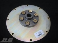
I'm thinking that they've used some sort of flexible joint that I've never encountered... that maybe they assemble one half on the flywheel, mount the other normal looking coupler half on the pump and adapter plate combination, then.. insert the tip of the pump's coupler half into the internal coupler half, and use the line the bolt holes up on the adapter plate and use those bolts to draw the pump/plate up against the bell housing, which forces the two flexible piece to mate.... something like the bottom picture is what I'm thinking.. because what I'm seeing inside had bolts on a smaller bolt circle than the flywheel. But, there's no provision for a holding the shaft with a set screw in that picture.

I don't know.

When it warms up below frigid, I'll go back up there and pry some more... maybe someone on here will recognize what kind of coupling/drive plate they've used in this thing and steer me in the right direction.

In the picture with the 3 red arrows, they're pointing out the bolts that seem to hold the inner half of the pump driving flexible joint to the flywheel. Couldn't really get the camera to focus down in there very well.

3.jpg

2.jpg

5.jpg

9.jpg

1.jpg
 
Given the access that you have with the wedges in place, I would be tempted to get a long Allen Wrench (or better, a short socket mounted Allen Wrench w/1/4" drive) and see if you can loosen that grub screw.

I hate any kind of set screw used in that manner - they always mar the shaft and create a burr which makes disassembly more difficult.
 
Your picture shows a bolt through a rubber grommet type coupling. It is used on older tractors to connect the crankshaft to the hydraulic pump. The rubber grommet will allow for some axial movement. The coupling cannot be completely withdrawn from the plate because the diameter of the head of the through bolt is larger than the diameter of the hole holding the rubber grommet.
 
SAE style bellhousings such as you show often have a tapped hole in the bottom of the housing.
 
I could be wrong, but looking at the problem from a common sense, mechanical standpoint, it would not require long special wrenches or a contortionist to assemble the thing. The pump bolts to the adapter and the pump/adapter combo is inserted into the female splined coupling and the adapter is bolted to the bellhousing.

I firmly believe that fretting/wiggling/wear has captured the splined pump shaft in the female spines of the coupling. Say some Hail Marys, wiggle and pry on the thing and I'll bet it'll come apart. Before I did that I would install long bolts through the adapter into the bellhousing to take pressure off the coupling and allow it to hang properly thus aiding in removal.

Ideally, the pump should come off with the adapter plate still attached to the bellhousing.

I'll be watching this thread with a hearty serving of 'crow' at the ready if my gut feeling was OTL!:o

Stuart
 
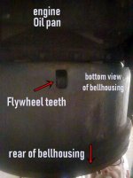
SAE style bellhousings such as you show often have a tapped hole in the bottom of the housing.

I haven't found any openings in the bellhousing, except for this one on the bottom. It at the "front" of it, lining up with the flywheel teeth.

1.jpg
 
I think I will put some longer bolts through the adapter plate to keep it from falling off should it come loose unexpectedly, and keep prying.

As far as "fretting" of a splined shaft... well, the pump shaft is visible and it's smooth.

It's not pulling out of that coupling. I can't really see much of that coupling, so it may be long and splined, fitting into some sort of female socket and that part is fretted.

When I pry the mounting plate back like shown, if the wedges slip out, the plate goes right back up against the bellhousing.

Makes me think that there's some sort of resilient material in there somewhere that just doesn't want to turn loose.

However this thing works, the rear half has to slip into the interior half, after being assembled, with no access to the interior for tightening any bolts.
 
My suggestion is stop prying before you break something expensive (practical experience). If at all possible drill an access hole to enable removing the bolts holding the drive plate to the flywheel. It can be somewhat out of line and use a flex socket. Then the drive plate should be easily removable or have a couple threaded holes to install bolts forcing it from the flywheel.
 
Some unsolicited comments. If this setup is to be used for a log splitter I sure would pick a much better, two stage pump. Having said that, the current pump and coupling method become moot and therefore subject to destructive disassembly, as in 'cut the sucker off and carry on'.

Stuart


Back
Top