What's new
What's new

OT - Urgent ! What is this electronic component spec ? (photos)

Milacron

Administrator
Staff member
Joined
Dec 15, 2000
Location
SC, USA
This on the backside of a diesel forklift ECU (computer engine control) board. As you can see it overheated and is now short in both directions. I'm assuming D stands for diode but the other identical appearance components are not conducting in either direction....could D stand for something else in this case ?

Also any hints on what the specs might be for replacement ? On some of the good ones I can barely make out the numbers 76 and 14 (size 7614 ?)
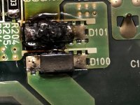
IMG_0147-1.jpg IMG_0146.jpg IMG_0145.jpg
 
7614 may be the date of manufacture: 14th week of 1976. Could it be that old?
Can you post a photo of the area surrounding the component?
Do you have a schematic?
 
They certainly look to be surface-mount diodes of some kind, and the standard code for such component is almost always Dxxx. There are many kinds of diode which are not interchangeable.

They cannot be size 7614, 76mm (3") by 14mm (0.6"), unless that circuit board is huge. How big are they in fact?

The photo is hard to interpret. Do you have a ring flash and/or a light tent?

When you checked the other Dxxx components for conductivity, exactly how did you do this?

The reason I ask is that diodes do not conduct below some voltage, and many ohmmeters use a test voltage low enough to not turn the diodes on, so the connecting circuit can instead be measured. Such ohmmeters will generally have a diode setting, which will tell you polarity and diode type (gemanium, schottky, silicon, GaS, ...). What is the make and model of ohmmeter you used?
 
Remember that the part that overheats is not usually the root cause of the problem. If you replace what appear to be diodes, they will likely just fail again. The circuit needs to troubleshot and you really need documentation to do that efficiently.
 
They are diodes indeed.... my probes were not penetrating the varnish earlier. Physical size of the body is about 2.5 x 5mm.

Using Fluke 75-III meter in diode mode to test
 
Remember that the part that overheats is not usually the root cause of the problem. If you replace what appear to be diodes, they will likely just fail again. The circuit needs to troubleshot and you really need documentation to do that efficiently.
There was a short in external wiring that has been found and fixed. ECU fuse was blowing before short was found (not blowing now) and hoping that is what caused this diode to fail.

De documentation, suspect that is hopeless. ECU is 2012 year (as is the Hyundai forklift), made by Denso in Japan. Model 275800-4232. The ECU is unobtainium...even Hyundai Industrial's main branch in Korea doesn't have any. (insane for a 9 year old forklift !)

Would like to order replacement diode Next Day Air from one of the usual suspects, but what spec to buy is the question.
 
Funny, on the one just below the one that is burnt the first character looks like a "V".

In an electronic lab if it couldn't be identified they would remove a good one and connect it to a curve tracer. From the displayed pattern the type could be identified.

On your board it could be a diode, schottky diode, or even a zener diode or semiconductor voltage limiter.

It would help to know what the maximum voltage might be and what components seem to be connected.

If you can supply better photos we might be able to look up the code.

PS: The actual SMT code should be 3 characters.
 
The part marking is most likely a part number, but could also be a lot code.

When I look at the pics, the first character looks more like a V to me. Searching V614 brings up some diode references that seem plausible - high voltage, high current, zeners which might have been selected for a hard duty use ECU...
 
If the first character is a 7, here are some possibilities.

7V5 - 7.5V 0.3W zener
7Y5 - 7.5V 1W zener

751, 752, or 753 - 7.5V 0.3W zener

73 followed by various characters - schottky diode 70V 50mA
 
When I look at the pics, the first character looks more like a V to me. Searching V614 brings up some diode references that seem plausible - high voltage, high current, zeners which might have been selected for a hard duty use ECU...
Looking at some others I'm thinking a V is more likely as well.
 
It would help to know what the maximum voltage might be and what components seem to be connected.
ECU input is 24V, IO output supposedly 5V.

Inputing V614 into search engine results in images that "look" the same as this one but it seems V614 isn't an actual part number. :confused:
 
They are diodes indeed.... my probes were not penetrating the varnish earlier.

Ahh.


Physical size of the body is about 2.5 x 5mm.

Hmm. For surface-mount devices (SMDs), the size code is tenths of a millimeter (not the whole mm I assumed before), so 7514 would be 7.5mm by 1.4mm, which isn't a standard size. Nor do they usually mark SMDs with their size, for lack of space for redundant data. So it's likely a device type ID code of some kind. There may be more data laser marked on the surface.


Using Fluke 75-III meter in diode mode to test

That will work just fine. What forward voltage drop does the Fluke report? That will tell silicon from schottky, but cannot tell a regular silicon diode from a Zener diode.

 
Limited resource field operations mode...

If diode then which one?

First, if there are many in assorted random looking places then likely NOT a unique item like a Zener but instead generic use like isolation or filtering.

Normal diode should work fine.

Voltage, on a 24 VDC item so whatever is handy should work.

Current, it smoked on a short so everything else was more robust than the diode.

Physical size may determine the current.

Measure one for size and pull up digi-key or other supplier and look for units same size to determine the range of current they are rated for.

Google image may find it...

Last, once you have idea of current range Amazon has many.

We found the exact replacement for some multilegged devices used in our chair lift.

Narrowed it down to what it was and current then looking at the offerings found one exactly same so we then discovered the exact item.

You could just solder in a 1N4004 1 Amp silicon 1 Amp diode there for testing.

Add a fuse to temp protect it maybe.

If it works good, if not troubleshoot.

Sent from my SM-G781V using Tapatalk
 
Was not aware that components like that were made in 1976.

If those are diodes then a similar one would replace it. Good designs do not depend on specifications of a particular component, especially for a garden variety dodee.
 

What forward voltage drop does the Fluke report? That will tell silicon from schottky, but cannot tell a regular silicon diode from a Zener diode.
Meter reads .550 on the neighboring (identical appearance wise) diodes.
 
Quick search pulled up D1F60 diode. Looks to match your size. 600V 1A. Datasheet below.

D1F60 pdf, D1F60 description, D1F60 datasheets, D1F60 view ::: ALLDATASHEET :::

If this one doesn't appear to fit, here are a list of others. For reference the diode size appears to be DO-214 (or SMA). There are a few on the list below that appear to match including a 2A version of the first one posted (FES2J).

The SMD components marking codes database - Starting with 'V6'
Would this one be a reasonable bet ? Physical size/layout and voltage seem appropriate....

https://www.mouser.com/ProductDetai...MIp5Hd1cuO9AIVBYiGCh3M-wbnEAAYASAAEgKdp_D_BwE
 
Would this one be a safe bet ? Physical size/layout and voltage seem appropriate....

https://www.mouser.com/ProductDetai...MIp5Hd1cuO9AIVBYiGCh3M-wbnEAAYASAAEgKdp_D_BwE

The two diodes you linked to had reverse voltages of 28V. The ones I found were 600V. Lots of assumptions and guesses on my end as I don't have the board in front of me. Can you take some more pics around the diodes (front and back of PCB) so I can see where these are being used?

Here is a link to Digikey with some of the diodes I'd try IF the 600V/1A rating is indeed correct.

Blocked
ECU input (and forklift voltage) is 24VDC hence my (questionable knowledge) thinking 28V diode... would 600V be safer bet and still work properly ?

Also I was so inclined to replace with exact same SMA package (due to space constraints with the cover) it had not occurred to me the difficulty of removing the old diode without risking trace damage...and therefore at least to get the forklift going I think I should use an axial type and solder the leads over the old diode and to hell with the cover for now. Any axial recommendations ?


Back
Top