What's new
What's new

problem disassembling a 3 jaw chuck

bytewise

Cast Iron
Joined
Dec 13, 2007
Location
Wappingers Falls NY
I have an old 3 jaw chuck that came with my Atlas lathe. It is seriously out of balance, but otherwise working OK. I decided to see if I could improve it. First I tried to take it apart. I have taken several other 3 jaw chucks apart previously without any problem.
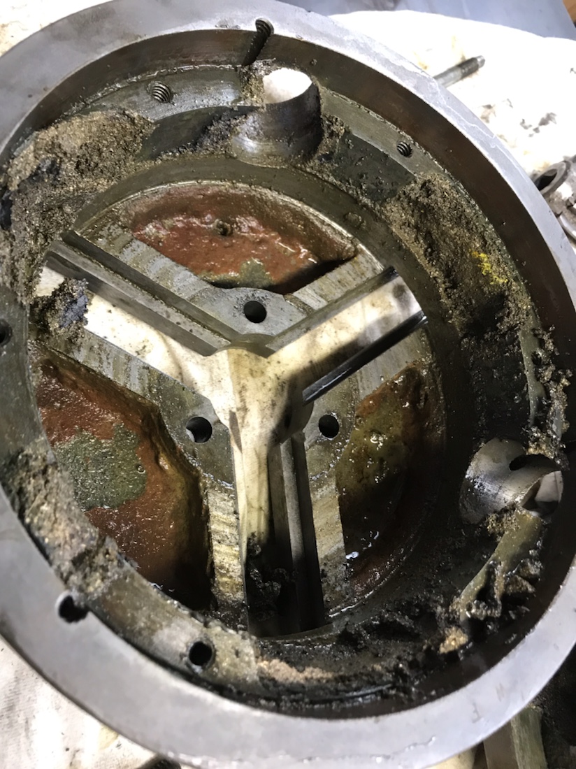
This chuck is 6 1/2 inch dia. made by Westcott Chuck Co, Oneida NY.
After removing the six screws around the outer edge of the back side and 3 screws from near the center of the front side, I tried to separate the layers. It appears that something is still holding on the side where the single adjustment gear is located. Also, after removing a round label on the face near the input gear, I found a hole. There are no obvious threads in the hole. The bottom of the hole seems to be the shape of a drill point. There is no sign of a hex socket or slot.
I wonder if this hole contains a lock pin to retain the input adj.gear?
The layers separate very slightly and then hang.
Does anyone have any information about this particular chuck?
I would appreciate any suggestions or ideas.
Thanks, Hugh
 
chuck

Put 2 of the 6 screws back in but not all the ways in and give them a tap with a brass or soft hammer the should separate the half's.
 
trouble separating

There is an surface of the inner part of the sandwich that can be accessed with a punch or press thru the jaw grooves. I have tried moderate pressing and hammering. The inner part moves just slightly all around but seems to be caught on the side near the input gear.
In the chucks I have taken apart previously, the input gears ride in bearing surfaces half and half in the two parts of the body. I wonder if this chuck requires the input gear to be removed before separating the halves?
The mystery continues.
Hugh
 
Some chucks have the small boss end of the pinion gear(s) fitting into a full round hole. But they have a threaded retaining pin in the outer rim of the chuck which is offset enough to permit the pin to pass through a groove in the outer circumference of the pinion gear, thus retaining it. But this should be readily visible from the back of the chuck.

Do you have the backplate off the chuck?
 
How about a pic for those of us with challenged imaginations?

Going back to Duckman's suggestion, put all six screws back in and tighten as though you were assembling.
Then loosen all six only one turn each and tap the heads. Loosen again and repeat as needed. You want the halves to seperate evenly without cocking. Test the pinion gear with the chuck key throughout this process- it should turn or at least wiggle a bit.

All of these chucks are pretty much the same. It's a wonder they didnt go bankrupt from suing each other after they copied each other's designs.
 
<<after they copied each other's designs>> ... except for Taylor - don't find many copies of a Taylor !

(Bit like André Citroën's herringbone bevel gears - who would ever think to try to copy something so friggin hard to make!)
 
more info

I can apply pressure to separate the two halves and when I do, it binds up the adj gear. I think HFD description of the structure is correct.
There is no separate back plate. The hub is integral to the back part of the chuck.
There is a hole in the front of the chuck that had a short screw covering the hole. This would be in the proper location for a retaining pin for the adj gear. (see pics) I do not see any way to grab the pin to remove it.
Suggestions are appreciated.
Hugh
 

Attachments

  • AtlasChuckBack.JPG
    AtlasChuckBack.JPG
    44.7 KB · Views: 1,406
  • AtlasChuckSide.JPG
    AtlasChuckSide.JPG
    39.6 KB · Views: 1,166
I have seen chucks like that before.

Remove the jaws.
You have to get those pins out at the pinion locations, use spray cleaner, turn the chuck face down pound on it with a soft hammer, use a thin magnet, or whatever.
Pull the pinions out.
Remove the screws on the back.
Then with a wood dowel, knock the back off by driving on the scroll though the jaw slots.

That style of 3jaw, is not the best.
 
I'd be really surprised that there are no internal threads inside whatever pin is down the hole. You might need to use a small slide hammer arrangement to pull the pin, although one would not expect it to be really tight, except for rust, etc. The slide hammer could consist of a long piece of the correct size threaded rod, a chunk of steel with a hole in it to slide over the rod, and a nut and washer on the top end of the rod to bump the slide against.

The chuck I have actually had a screwdriver slot on the top of the retaining pin itself, and it was readily backed out of the hole.
 
I give up

The pin has no hole. I tried to drill it. It is so hard the drill would not touch it.
I decided to drill the balancing adjustments on the back of the chuck instead of inside.
It seams that this chuck was never intended to be disassembled!
Thanks to all for the suggestions.
Hugh
 
I have a 3-jaw chuck of the same make that I took off a Kearney and Trecker index head. It only has one set of jaws that are meant for OD gripping. I used the D-3 cam lock backing plate that came with my newly acquired South Bend heavy 10 lathe. The chuck had 1/2 16 tpi cap screws to attach it to the index head spindle nose. The back of the chuck had keyways to accommodate the driving lugs on the index head spindle nose. After dorking around making inserts to reduce the 1/2" cap screw holes to accommodate 5/16-18 screws to fasten the chuck to the cam lock backing plate, I was able to use the chuck on my lathe. The chuck was very accurate (repeated within .002 TIR or less every time.) It was horribly out of balance. I considered taking it apart, but I'm glad I didn't. I took the jaws out to clean it up, and I had a difficult time getting them installed again in the right order.

I have done this hundreds of times on other 3-jaw chucks, but I had to remove the jaws and replace them 4 times before I got them right. There were no markings on the jaws or the jaw positions of the body of the chuck. So it was sort of trial and error to get them in the right place. Another problem was that the jaws did not fit interchangably in the jaw positions, they were either to tight or too loose. I finally got them in the right positions where they repeated accurately.

Another thing that I noticed was that the grooves in the chuck jaws that mated with the keys in the in the corresponding positions in the chuck body were not 90 degrees, as in normal chucks. They were angular, which contributed to them not being interchangable.

Another singular circumstance was there was a white, clay like substance in the grooves on the sides of the chuck jaws, which I scraped out. I think that this was used as a filler to make the fit of the jaws more accurate.

Also the movement of the jaws when adjusting them to change diameters is terribly slow.

The conclusion that I made was that this chuck was not made for lathe use because it has the letters WS attached to the model number, It is a very accurate chuck with limited use for gripping OD's and nothing else, and is meant to stay on the spindle nose of an index head, where high-speed balance problems are not an issue. It isn't meant to be taken apart, as it was apparent that the jaws of the chuck were painstakingly fitted to their individual position, and the out-of-balance would shake the s--t out an Atlas lathe, unless operated at the slowest speed in back gear. Do not fault the manufacturer, it was made for a specific use, which is not the use that you would like to use it for.

In conclusion, it will go back on the index head as soon as I can replace it with another D-3 cam lock 3-jaw chuck. It was not meant to be used on a lathe. I doubt if your chuck was meant for a lathe either, you may find this out if you take the back plate off. Look for letters after the model number or serial number, these may give you a clue as to the index head that it was meant to be used on.

Hi to Ferrous Antiquos, who sold me the Heavy 10 terning lay. I made the trip to Lawn Guylin to pick it up this summer.
 
more info re:balancing a chuck

I was able to balance the chuck by drilling some shallow holes in the back face of the chuck body. I still had some shake in the lathe so I took the head apart. I found that the large back gear was out in spite of factory drill holes to improve the balance. After drilling some more holes it was good. I reassembled the whole thing and now the shake is almost all gone at the highest speed. I think this is as good as I can do with my tools.

While trying to go to sleep, I thought of a way to disassemble the chuck. Drill a hole from the face exactly in line with the pin. The pin should be able to be driven out. When cleaning etc is done the extra hole can be tapped and a set screw installed to close the hole and retain the pin.
I might do this sometime in the future if I need to clean the chuck.
Hugh
 
The pin should drop out sans corrosion. If you have the jaws closed or open all the way, some force may be levied against the pin. Also, using your chuck key, wobble the pinion while the chuck is inverted on the bench.
 
This post is almost 4 yrs old, I'd imagine that chucks already been melted down into a brand spanking new South Bend already. Dave [acme thread]
 
This post is almost 4 yrs old, I'd imagine that chucks already been melted down into a brand spanking new South Bend already. Dave [acme thread]

Just wanted to drop in and point out that now another 5 years later, I'm reading through threads on chuck disassembly. Whenever somebody adds useful information (neither of our posts count there) it may benefit someone far down the road.
 
A 10 year old thread helped me today. :)

I have a Westcott chuck that came on the SB 13" I just bought. Could not get it apart until I say this thread (and some others). I didn't know there were pins holding the pinions in.

BUT, I got lucky! Someone, perhaps a previous owner, drilled and tapped 3 opposing holes in the back of the chuck and inserted set screws. You can see them in the below picture. With both sides removed, getting the pins out was a breeze.

What I found inside almost made me wish I hadn't. Oy.

img_2963.jpg
 
Many ages after the OP, I too am having major problems disassembling a three jaw chuck! Long live this thread!

My chuck appears to be maybe for a South Bend 10* (2-1/4 x 8tpi spindle thread) stamped on it are "Made in England" and " Model 101.21680". It seems to have the backplate only held on by the six machine screws. After much penetrant, a long time with a heat gun and much tapping on longer screws...it's still good and on there. I see no holes for pins, no other screws or bolts and no access holes when rotating through the scroll.

I can see a seam that runs around the circumference, passing through the chuck key hole, but only because oil residue seeped out when heating/tapping. I haven't been able to produce any noticeable gap.

Any tips to get this apart? I thought of holding something in the jaws and using a gear puller against that just to break it free ( I'd probably only get a tiny movement before the jaws stopped holding), but the fingers on my puller are too big to fit and I'm not entirely sure I wouldn't damage something internally.

Pics, as I seem to not have permission to upload here:
IMG-3090 — ImgBB
IMG-3091 — ImgBB
 
Is there a spot in the front for some jack screws? These are often an interference fit between the chuck and the back plate and the maker provides some threaded holes in one piece, with solid material in the other piece. When you thread bolts or screws in, they push against the second piece.
 
I have no advice on chuck disassembly, I will just note that the form of the chuck part number is the way Sears and Roebuck numbers everything. Digits before the period corresponds to a manufacturer.
Gonna go out on a limb and say this chuck was originally on a Atlas/Craftsman lathe sold by Sears.
 
Old thread but I will add that the last chuck I took apart I mad e a very slight modification to make it a lot easier next time. It came apart fairly easy once I opened up the joint between front and back enough to get a lever in. I had to use a sharp wood chisel to get it started. Once it was apart I placed one half on the milling machine, inside up, and milled a shallow 1/2" wide groove on the edge at two opposite sides. These will allow a screwdriver to pop the two halves apart next time. Not enough metal was removed to really affect balance.
Bill D


Back
Top