cash
Titanium
- Joined
- Aug 8, 2007
- Location
- Greendale,WI
I am looking to see if somebody has a chart/info on what the ratio is on the fit for in my case what would be on a cast iron bearing. I know it this info has to be in the Bible somewhere.
To be specific I am trying to confirm how the fit on my carriage bore should be in comparison to the table on a 120" Blanchard we are rebuilding.
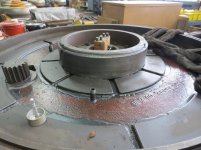
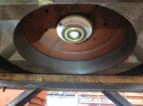
The pinion gear and bull gear are terrible worn, so this is why I am doing some further checks. The bores do not appear to have any major wear or scoring.
The table rides in an oil bath and the hub is lubricated via the diagonal grooves to draw oil up the hub/bore. Table rotation is a max of 12 rpm.
The diameters I am working with are 21.375" and it has about 4.500" width of contact area.
We are thinking up to 12' a standard of .0005" per inch is used. After this we are not sure.
To be specific I am trying to confirm how the fit on my carriage bore should be in comparison to the table on a 120" Blanchard we are rebuilding.
The pinion gear and bull gear are terrible worn, so this is why I am doing some further checks. The bores do not appear to have any major wear or scoring.
The table rides in an oil bath and the hub is lubricated via the diagonal grooves to draw oil up the hub/bore. Table rotation is a max of 12 rpm.
The diameters I am working with are 21.375" and it has about 4.500" width of contact area.
We are thinking up to 12' a standard of .0005" per inch is used. After this we are not sure.