Hi Guys,
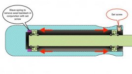
I have a 304 steel handle assembly that rotates on two ball bearings. The bearings are secured in place with low clearance c-clips. The handle slides over the bearings and is secured in place with a set screw. On the opposite side of the set screw, a wave-spring provides tension and removes the axial backlash.
I am straggling to remove also the radial backlash. Normally I would press-fit the bearings or use a bearing retaining compound but I have the requirement for the assembly to be disassemblable by hand, with only an Allen key for the set screw. This means that the bore interfacing with bearing's OD should be a few thou larger than the OD of the bearings. See picture below.
The handle will take a maximum load of 20 lbs (10kg) with very low RPM and used sparingly.
Would a low-strength retaining compound work? Could it be disassembled manually? What else could be done?

Thanks in advance!
Dimos
I have a 304 steel handle assembly that rotates on two ball bearings. The bearings are secured in place with low clearance c-clips. The handle slides over the bearings and is secured in place with a set screw. On the opposite side of the set screw, a wave-spring provides tension and removes the axial backlash.
I am straggling to remove also the radial backlash. Normally I would press-fit the bearings or use a bearing retaining compound but I have the requirement for the assembly to be disassemblable by hand, with only an Allen key for the set screw. This means that the bore interfacing with bearing's OD should be a few thou larger than the OD of the bearings. See picture below.
The handle will take a maximum load of 20 lbs (10kg) with very low RPM and used sparingly.
Would a low-strength retaining compound work? Could it be disassembled manually? What else could be done?
Thanks in advance!
Dimos
")
")