What's new
What's new

Rockwell Delta Vert Mill - Power Feed Potentiometer

simonstjames

Plastic
Joined
Feb 3, 2020
Location
LA
Hello,

First post and hoping for help.

I have a Rockwell Delta Vertical Knee Mill 21-100. I purchased it not too long ago as it was the right size for me and just got around to really putting it to use. It has a the Variable Power Feed. The feed has worked in the past, rapid feed/movement is fine, but the potentiometer and speed adjustment has been spotty and finally gave out giving me no speed adjustment whatsoever.

I took out the circuitry trying to find some info to get replacement potentiometer. Tracked it down to be a Mallory potentiometer with marking 'M1MPK V13' on the back, nothing else. After more searching I found a catalog which said M1MPK is a 1kohm 4watt.
Ordered a clarostat 1k 4watt replacement which didn't work.
I tracked down manuals on manuals about the RD 21-100 and the powerfeed. I can't find anything as to what the exact specs for the potentiometer were even on the replacement parts list.

So I ask for your help. Is my information correct? Does anyone have the exact specs on the power feed and the potentiometer needed? Is there a newer/more efficient part to use? Can I refurbish the potentiometer? Circuitry is not my forte. Pictures attached, any help is appreciated.

Thanks.


I diassembled the motor (mostly to adjust the mounts and
 

Attachments

  • IMG_9083.jpg
    IMG_9083.jpg
    90.8 KB · Views: 219
  • IMG_8776.jpg
    IMG_8776.jpg
    88.4 KB · Views: 135
Looking it up on the web, I found that part number listed at anything from 1k ohms to 3 k ohms.

Either the "M1MPK" part is only the mechanical style, which is quite possible, OR the folks showing it are clueless. Mallory made replacement parts, and their part numbers are often goofy and unlike most others.

The thing to do, if the control is not shot, is to measure with an ohmmeter. If the slider is flaky, a common problem, you can measure between the "outside" terminals of the three.

It may be an end connection that is bad, so then measure between whichever of the outside terminals givs a reading, with the other ohmmeter lead on the middle terminal (the slider). Turn the shaft to get the maximum reading, and if that occurs pretty near the end of rotation, the reading you get is the overall resistance, which is the number you need.
 
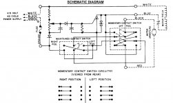
That is a nice feature on those mills... when it works correctly. It may not even be the pot that went bad. Does the rapid feed still work? If the rapid still works it may be something else in the variable speed part of the circuit. Switching to rapid bypasses the variable speed circuit and "full fields" the motor. The armature always has full line voltage when the unit is on. Here is a link to the manual complete with a schematic on the variable speed circuit: http://vintagemachinery.org/pubs/2793/4232.pdf The page of interest is page 62 (or 65, depending on your PDF reader.)

-DU-
 
Your logic seems to be OK. The "13" on the end of the part number does look like a value in Ohms: a 1 followed by 3 zeros. But different manufacturers and even the same manufacturer have been known to use different styles of creating their part numbers.

It appears to me that all the wires to the pot are the same color. And I can not tell if there are two or three wires going to it. This makes me wonder if a wiring mistake may have been made when the new part was soldered in.

Yes, you can almost always check the value of a pot with an Ohm meter on the two outer terminals. Most pots fail at the wiper or center connection so they will still read the proper value across the outer two terminals; like a fixed resistor. And don't get too worried if the value measures a bit off of the nominal value. With 10%, 20%, and even larger tolerances being common, a 1K pot could easily read 700 Ohms or 1.3K. Electronics is not precise to three or four decimal places like a micrometer or even a caliper.

If it has three wires, you may have mixed them up when installing the new part. Again the VOM (Volt Ohm Meter) is your friend. One wire should be ground and one should be a direct connection to the positive power Voltage. If you can locate these points in the circuit you can, WITH POWER TURNED OFF, use the Ohms scale to check for these two wires. They should read ZERO Ohms on a low resistance scale (1X) to one or the other of those circuit points. Those two wires would go to the two outer terminals of the pot. And the third wire (odd man out) should go to the wiper.

Possible problems:

If the pot works backwards (low = high speed and hi = low speed) just reverse the outer two wires.

Your replacement pot may be defective. It also can be checked with a Ohm meter. The two outer terminals should show the rated resistance and from each of those two to the third terminal should show a uniformly varying resistance with no jumps as the control is rotated.

Even an inexpensive VOM is a great test instrument. In my professional career, I could have done about 80 to 90 percent of my electronic troubleshooting with a $10 VOM. In fact, I had such a meter in my tool box at all times. If you don't have one and need to conserve funds, your first VOM can/should be an analog one.

PS: Perhaps I am missing something, but I see nothing of value in your first photo. And your second photo would be a lot more valuable with the wires untangled and the terminals visible.
 
As mentioned earlier, the pot may not be the problem. I doubt that you have a decade box around but there are some things you could try. Remove the pot and use some alligator clip jumpers to insert various fixed resisters in the range of the pot. See if the speed changes. If it does and follows a logical pattern, then it is probably the pot. If not then it is something else.
 
I'm currently rebuilding the power feed controls on my 21-122 hor/vert Rockwell. The pot is a 1k. The pot doesn't directly control the voltage that's output to the motor though, the SCR (aka thyristor) does. Yours has a modern SCR already so it has been replaced at some point. Put your ohm meter across the potentiometer and see if the resistance changes with position. If it's working properly, put your ohm meter across the legs of the SCR and see if the voltage changes as you change the resistance of the potentiometer.
 
I have the same mill but no power feed. There are some folks that have converted bridgeport type feeds to this mill. It does involve making a leadscrew extension and machining a housing adapter, among a few other things. Something to keep in mind if the old one is not repairable. I plan to do this at some point.
 
First post and offering help. I can't address the feed speed problem but I can give you CORRECT information regarding the Mallory pot. The sort-of bar-M symbol was a Mallory trademark. The M1MPK is the Mallory part number, including the resistive value of 1k (1000) ohms. The V13 is I-don't-know-what but is irrelevant. Mallory part numbers were straightforward and not obscure. The M1MPK is definitely 1k ohms. The V13 or 13 has nothing at all to do with the value. The "M" series was available in 18 values from 1 to 100k ohms, each with a clearly distinct part number.

Yes, you can easily check the pot if you have even a very modest multimeter. Either an analog or digital one can measure the end-to-end resistance of the pot's element between the outer terminals. It should be 1k ohms +/-10%. It's much easier to measure the progression of the resistance, from the center (moving) contact to either end, with an analog meter but it can be done with a digital if you work slowly and try to relate every small amount of rotation to an appropriate increase in resistance reading. That pot should have a so-called linear taper, meaning that each increment of rotation imparts a similar increase in resistance.

I have no idea of the circuit involved here but only be concerned about replacing the pot if it can be proven defective. Even if it's 'jumpy' or intermittent it might respond to cleaning, which isn't too difficult with a little guidance. Any questions, feel free to ask and I'll try to make sense.

I searched for an M1MPK to check present prices on Ebay. They're long out of production but are still needed as replacements for a particular couple of pieces of electronic instrumentation. I happened to see the hit to this forum and your post. I joined in case I might be of help.

Fred
 
Thank you all for the help, and sorry for the delay in my response.

I did some testing with the advise given. I have a multimeter and was able to test both the new and old pot. Both seem to give clear readings and clear readings while adjusting the contact. Old meter measured around 1000 ohm and the new was at 1200 ohm.

The wires to the pot were not color coded, but I did mark them prior to taking the old pot out. Everything went back into the correct position when I put the motor/circuit back together.

All in all, even with the testing, trouble shooting, pot cleaning, and proper placement of all the wires, I still can't get the feed adjusted. The motor feed has rapid and variable speed toggle switches. Both work even with the pot disconnected, the motor will simply operate at full speed.

Someone had mentioned the thyristor/scr. Could that be a possibility?
When I first got the mill, the feed worked fine and was fully adjustable. It was a little finicky towards the end and seemed to go in and out of adjusted speed until it just didn't act as a variable feed and let the motor only run full field.

Appreciate the help.
 
Yes, the SCR would be my guess. It sounds like it is opening fully regardless of what is applied to the gate. If the potentiometer is functioning properly and the switch is working properly, I can't really think of another likely culprit besides the SCR. The only other components are a RC circuit to rectify the AC voltage and a TVS diode to absorb voltage transients.

Here is the SCR I ordered to replace the thyristor on my board. But since yours worked previously, you may want to just order the same one if it has a p/n on it. I honestly don't know enough about SCRs to tell the difference. I had a buddy who is an electrical engineer look at my circuit and make a shopping list for me :-)
 
There are a few candidates for failed semiconductors in that drive circuit. The SCR, a couple of
rectifiers, and a peculiar item called a "Diac" which helps to provide the trigger for the SCR.


Jim
 
There are a few candidates for failed semiconductors in that drive circuit.

And "not only". Ask yer electrical guru for "the REST of" the Bill Of Materials story.

It is small enough, has low-enough parts count, all of them cheap, and/or easily substituted, I'd suggest simply putting it on the bench, generating a FULL "BOM", collecting the parts, then building a "clone" of it, with ALL new parts. re-using nada - not even the boards. Pre-drilled "perf" board has extra holes yah do not use all of? So what? Not a lot of drilling needed, either!

:)

Really. It is that simple, as such devices go.

So it can actually be faster to build, new, than to waste the time anal-eyes-ing old.

And it leaves fewer uncertainties as to what might be marginal and want to fail NEXT.
 
Exactly the route I am going :-) I ordered replacements for all the components except the switches and a solderable breadboard to hold it all. No drilling necessary! Why not replace the switches? Well, mine worked fine and I wouldn't even know where to look to find a switch equivalent to that momentary switch...
Power Feed Schematic Original.JPG
 
There are a few candidates for failed semiconductors in that drive circuit. The SCR, a couple of
rectifiers, and a peculiar item called a "Diac" which helps to provide the trigger for the SCR.


Jim

Where is there a diac Jim? 'Cause I wasn't figuring to use one...
 
I wouldn't even know where to look to find a switch equivalent to that momentary switch...
View attachment 279853

Yer on the right track, then.

A switch? Schematic shows an ignorant 4PDT or "3T" if yah count a CENTER-OFF (or UNUSED third set of poles, which works just as well) and shows break-before-make contact form. I'd expect it to be "MOM" action, both sides of center, then?

Not uncommon at all. Possibly as close as my "Hell Box" for managing my DC Drives?

:)

Get us such physical size/space details as you can.

If I don't have it, I can probably ID a replacement - even an improvement.

Ex: I'm fond of momentary toggles as I stash those durable oil and coolant proof "Hexane" (the trade-name, not the solvent) flexible elastomer boots as KB use on their "washdown" NEMA 4X housed DC drives. Cheap enough in ten-packs. I use ignorant natural tan, but they make those in useful to indicate function or grouping-of colours as well.
 
So "type 3" was the search operator I was missing! Now I know. I'm gonna stick with the one I have for the time being though. That thing has to handle 120 VDC so a replacement isn't cheap. I sure appreciate the information though!

If I'm wrong about it being expensive, I'm happy to be enlightened though! I don't have the switch with me but it's a panel mount and I'm gonna guess it's 2"x2" roughly. But there's space for it regardless. I'll be attaching it to the board with flying leads so it won't have to fit the hole spacing. Can be solder lug, screw term, faston tab or whatever.

Thanks for your feedback!
 
So "type 3" was the search operator I was missing!

"3 "THROW", not type.

EX:

SPST MOM - Single-Pole, Single Throw, MOMomentary, Average doorbell switch.

The rest are oblivious enough. SPDT, DPST, DPDT, SPDT Center OFF, SP3T...etc.

The contact "Form type" also has standardized codes as well. Form A, B, C, etc that indicate if break before make, make before break / "transfer", and so on.

Then there are "T bar" switches as can make even a multi-wafer stacked rotary look simple!

"Wafer' switches can have contacts that cover multiple positions, or come and go, alternating or skipping one or several positions and working with multiple "layers", stacked. OTOH, they clearly show themselves for what they do.

Radio, Military weapons systems, and even the basic Telco industry are to blame for a lot of this.

Old Skewl "hook switch" looked like just that, two-piece phone era. Simple "hook", literally. But only on the outside.

Stack of multi-function mechanically-staged contacts on the INSIDE was more challenging!

UNfortunately? Most "modern" gear uses deceptively simple switches.. to cause "logic" to do insanely complex tasking.. from heirachical menus of lookup-tables... that are themselves constantly dynamically altered!

Multi-button mouse on a Pee Cee, doing browsing or editing for example.

It's all mode and context sensitive...

:(
 
So "type 3" was the search operator I was missing! Now I know. I'm gonna stick with the one I have for the time being though. That thing has to handle 120 VDC so a replacement isn't cheap. I sure appreciate the information though!

If I'm wrong about it being expensive, I'm happy to be enlightened though! I don't have the switch with me but it's a panel mount and I'm gonna guess it's 2"x2" roughly. But there's space for it regardless. I'll be attaching it to the board with flying leads so it won't have to fit the hole spacing. Can be solder lug, screw term, faston tab or whatever.

Thanks for your feedback!
Hello

I recently aquired an original 21-820 Rockwell power feed, and the circuit board has a blown electrolytic cap, blown diodes, etc., and I'd like to rebuild it as you mentioned you were doing. Do you still have the replacement component part list you came up with, and if so, could you post or send to me?

Thanks very much.

Chris
 
Exactly the route I am going :-) I ordered replacements for all the components except the switches and a solderable breadboard to hold it all. No drilling necessary! Why not replace the switches? Well, mine worked fine and I wouldn't even know where to look to find a switch equivalent to that momentary switch...
View attachment 279853
That switch is a 4PDT (4 pole, double throw) momentary-off-momentary, toggle switch. Digi-Key is one place to look up such stuff.
At US$98 for one it is a bit hefty on price. You can almost certainly find one that is less expensive BUT Digi-Key does say they have 47 in stock. You can get the price down to US$15-25 if the amp rating is lowered to 5 amps. The one listed in the link is rated at 15A, 125V. It is a 115V (per the diagram) circuit and according to the manual it takes a 4 amp fuse so a 5 amp switch should do it. Personally I would prefer a heavier switch because it is to be used in an "industrial environment."


Back
Top