What's new
What's new

Rotary Axis ( 4th Axis ) Fixturing For Vise

Zahnrad Kopf

Diamond
Joined
Apr 5, 2010
Location
Tropic of Milwaukee
Was just getting ready to order a Stallion Trunnion table for 4th axis use ( having failed to find a used one to possibly purchase ) when I started considering that this needn't have to a full-on typical trunnion style application. The reality too, is that we simply would not use this enough for me to feel good about spending that much money on its purchase.

09_big.jpg


What I want to do is rotate a part ( held in a vise in the traditional manner ) to enable milling features and pockets on an angle from horizontal. It occurs to me that people here have more than likely needed to do the same type of thing and found fixtures and accessories that I am completely unaware of, so the logical step is to ask what you've found and used.

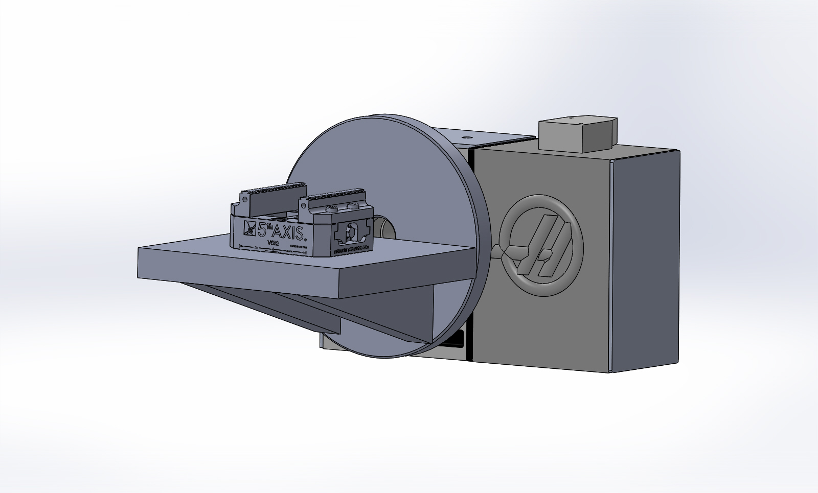
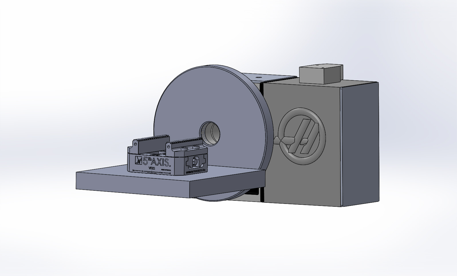
I'd be very tempted to mount our 5thAxis V562 on an angle plate that attaches to a face plate on the 4th axis, but the fact of the matter is that it is too small for this stock and the whole contraption wouldn't fit on the face plate with enough surface contact to insure rigidity. However, I am going to look at making an alternative mounting arrangement for it in effort to accomplish this. For now, though... what have you used or are aware of that accomplishes this type of arrangement?

V562sm.png


Thanks.
 
Years ago I had a job that I REALLY needed some type of a tombstone or vise for the
4th..

After I picked my self up off the floor and pulled my jaw up off my chest from the
sticker shock...

I took a big chunk of A36, squared it up, put a triangle on one
end and a center in the other and went and got some mit-e-bite's.
Took a few hours and a only a few dollars, I was able to run 4
parts at once... Worked great..
 
If you're not going to use it that often, I'd suggest building your own. The V562 is too small for your part? I'd say do like bob recommends and use some miteebites on something simple?
 
I would 2nd building a tombstone with a mitee bite fixture.

I looked into a Chick set up a couple years ago. I too had to pick myself up off the floor.
 
We run several parts with MiteeBites on a dedicated chunk in the 4th axis.
Just like BobW describes, clamped on one end, and center drilled on the other.
Sometimes just a drilled hole, and an intersecting 1/4-28 brass tipped set screw to secure the part.
Up to 32 parts at a time, on multiple sides all at once.
 
Ive done it both ways you described. You're obviously smart enough to know what will work for your app. Sounds like you're getting into bigger parts. Maybe the trunnion is a good idea. I made one myself a while back. Even put a rotary on that. Your right, dont get used all too often. BUT, it IS handy as fuck when you do need it. You know you're welcone to visit, maybe it would work for you.
 
This is my current best solution to this problem. 2" in the photo but I have 3" and it would be easy to scale up for larger versions.

2in-vise.jpg

Future best solution is to make it 4 sided in the next 6 weeks, next is to double the length to hold 16 parts. Turns out aluminum vises are not that difficult to design or make, at least not compared to a plastic injection mold.

I used to rely on making custom fixtures using Uniforce style clamps to hold the parts. Downside is the clamps will bow the fixture if not tightened uniformly, too much work for a new fixture, and generally can't repair the fixture if a station is damaged. I have always held my 4th axis fixtures between the 4th and a tailstock. Currently it takes around 20 seconds of spindle downtime to swap them between cycles.
 
This is my current best solution to this problem. 2" in the photo but I have 3" and it would be easy to scale up for larger versions.

View attachment 214993

Future best solution is to make it 4 sided in the next 6 weeks, next is to double the length to hold 16 parts. Turns out aluminum vises are not that difficult to design or make, at least not compared to a plastic injection mold.
How is that clamped? Is it just the force from the tailstock?
 
Thank you for the responses, Gentlemen. I appreciate it. To better elaborate, confirm, and explain more betterer -

Yes, we can CERTAINLY make something well executed. However, I have had my back against the wall with regard to time available. In fact, everyone that knows me in person knows that this is the norm for us. I usually make our fixturing and workholding. It is the default condition that we operate under. This time, I was thinking that the time savings would be better applied to making parts and I'd be better served to just suck it up and spend the money. I'm just finding it difficult to justify spending ~ $3,000.00USD on something that won't be used very much. And there are only ten or so parts on this one, too. ( as FK rightfully points out, though - when you need it, you need it. )

The parts themselves are very irregularly shaped, and don't lend well to a vise for all operations, but do start out from rectangular blocks. There is an existing fixture that they were run in, for some of the ops. They were previously being run somewhere else and took several ops on a few machines. ( can't go into too much detail, sorry ) My goal and thinking is that I can get them to run complete, in one machine and set up if I do this correctly. They are basically a large, vee shaped "knuckle" protruding from the Y+ edge, in the middle of a 6.5" x 6" plate that is 1.5" thick, and one end has a large "thumb" sticking out the same direction as the vee knuckle. The periphery of the Y+ edge has two angled surfaces along its length ( almost like relief on a cutting tool ) and there are pockets in the part that are also machined on angle.

I can get to it all with four angular indexes. And I think I should do so... Hence this rabbit hole.

This is all compounded by several factors where nothing is optimum. We're under a time constraint. The material is H13. Or D2. I can't recall at the moment... Will clarify that tomorrow.

FK - Yes, Sir. We are indeed being dragged into larger and larger work. This is part of the ... errr... "issue" is not the correct word, here. "Considerations" is better, but not wholly correct... We're doing more and more D2, H13, A2, etc... So the actual machine and tooling demands are also increasing. At this moment, we have the CAT40 machine. A Haas. It's not the best choice for some things, but it has served us well and gotten us to this point. I really need through spindle coolant at this point. And larger machine testicles, too... And more room... And possibly a full time employee... and ... and ... and ...

As of this week, we are looking for a new building. It's time. But it is not going to happen tomorrow. ( thankfully ) We also have a CAT50 machine coming. Slightly larger than this one, with 40 x 20 table travels, through spindle coolant, and 12K spindle. But it won't be here and set up for some time. So I just need to suck it up and get through this stuff...

It's all good stuff, but no matter what there is always some kind of headache to address...

I will absolutely stop by. It just will not be for at least a few days. It's simply too busy to allow me to leave the shop for any time span longer than relieving my bladder. :eek:

Thanks Gentlemen. I appreciate all the input and experiences.

EDIT - Oops. I forgot - this is were my thinking is at right now -

I already have the faceplate made up from earlier work. The rest would be 1.5" Cast Iron, or Steel Plate.

ViseRotaryFixture.JPG
 
Zahnrad- From what you describe your solution sounds pretty good to me. Other than getting the workpiece closer to the 4th axis center I don't see much room for improvement. That dovetail vise could hold a pretty big part.

Mud- It is a pneumatic tailstock good for 370 lbs at 60 psi, which is the maximum load for the 4th in this direction. How much pressure I set it for depends on the need.
 
Other than getting the workpiece closer to the 4th axis center I don't see much room for improvement.

I agree. The problem that I run into is that if I offset the "platten" that the vise sits upon, so that the top of the vise jaws are at centerline, there is precious little room for any stiffeners/braces underneath it. See pic.

ViseRotaryFixture1.JPG
 
Yeah, it's a balance. Can you put some bracing on the vise side of the platen as well? There is no reason the platter plate needs to be full round. Trimming it down may give you more clearance for your parts, and add a little more material where the platten attaches to the platter. How much extra work to just machine the platter and platen out of a solid block of cast iron? It would sure make the connection between the two solid with big radiuses where they come together, just a thought. Also no point in having some much platten extending around the vise body, if you make it from one block you could sure trim the size down from what you have modeled.
 
Yeah, it's a balance. Can you put some bracing on the vise side of the platen as well? There is no reason the platter plate needs to be full round. Trimming it down may give you more clearance for your parts, and add a little more material where the platten attaches to the platter. How much extra work to just machine the platter and platen out of a solid block of cast iron? It would sure make the connection between the two solid with big radiuses where they come together, just a thought. Also no point in having some much platten extending around the vise body, if you make it from one block you could sure trim the size down from what you have modeled.

All of it good suggestion. I've had the same thoughts. My answers in effort to suss out more options, are that the face plate needn't be full 12" in diameter, but that I do have one of those at the ready. Too, I'm perfectly willing to cut it up, but can only go so far, as the interface is actually an A2-6 spindle nose. I'd rather have a slotted face rotary, but this is what was available to install at the time. So, tooling needs to accommodate it. The taper register of it is 4.1875" at the large part and the hole pattern is on both sides of it, so it would theoretically be possible to use the inner one... So one could theoretically use a 6" x 6" x 12"ish lump to start with and blow out the middle, leaving one end for the spindle nose mate and the other end for tailstock interface. ( or not as the case may be )

I'll muddle about in CAD and see what strikes my fancy, but I would STILL rather purchase something like this if it exists. Would save so much time and effort. I really need to keep working on the jobs that are in process now. Not making tooling/fixturing.

Thanks.
 
You are mounting it on a Haas, how rigid does it need to be to be more rigid than the rotary table? The 5th axis vise you show appears to be the answer to a vise on a trunion table, but I question its rigidity as well, especially when cutting tool steel.

I think the design you show will be be plenty rigid if you weld it rather than bolt it. If you must bolt it, relieve the center so the bolting forces bear on the outsides of the joint. If you weld it, machine the back for the rotary table. Machine the working face after installation.

Kurt also makes a variety of vises similar to the 5th axis vise you show.
 
Can you buy/build a tailstock for the scheme in your picture? A tailstock that matches that rotary would seem to have better general utility than a fixed size trunnion.
 
Last edited:
You are mounting it on a Haas, how rigid does it need to be to be more rigid than the rotary table?

I operate under the consideration that anything worth building is worth overbuilding.

The 5th axis vise you show appears to be the answer to a vise on a trunion table, but I question its rigidity as well, especially when cutting tool steel.

I have always been pleased when using it for the last number of years. It's been a real boon. Admittedly, I have not subjected it to cutting 1.5" D2 yet...

Kurt also makes a variety of vises similar to the 5th axis vise you show.

I've seen the Kurts and have been flatly unimpressed. Much more satisfied with the 5thAxis, Raptors, and a third that I cannot recall at the moment.

Can you buy/build a tailstock for the scheme in your picture? A tailstock that matches that rotary would seem to have better general utility than a fixed size trunnion.

A tailstock is obligatory for these types of things in my opinion. It's not in the pictures simply so it doesn't obscure the view. There is a tab/boss that rises off the platen that the tailstock engages.
 
I agree. The problem that I run into is that if I offset the "platten" that the vise sits upon, so that the top of the vise jaws are at centerline, there is precious little room for any stiffeners/braces underneath it. See pic.

ViseRotaryFixture1.JPG
You have room for 1 stiffener in the center bottom and you have the height of the chuck available for 2 more on TOP of the plate. Should be sufficient for your needs. Just turn the chuck 90° to get clearance for the chuck wrench, and that also allows you to move the stiffeners in close to the chuck body for clearance. No real need for the plate to be that wide either, and narrowing it up allows better clearance to the spindle.
 
I've seen the Kurts and have been flatly unimpressed. Much more satisfied with the 5thAxis, Raptors, and a third that I cannot recall at the moment.

Probably Lang.

If the rotary is beefy enough and you can get close enough to it, you don't need a tailstock. I've seen a couple of places running Robodrills in production that just have a big steel tombstone bolted directly to the faceplate. They only started to have problems with the DDR tables and running aluminum really fast/hard. A more rigid table would have solved that problem. In my Speedio setup, this is what we're exploring, running a Sankyo table (it has the beefiest bearings and a backlash free crazy gear design):

7fUWXPs.jpg


One side of the S700 table taken up with the rotary, other side has a sub plate with Orange ball locks where the dovetail prep and 2nd op can be done, so we will be getting 3 full sets of parts (multiple parts from each piece of stock) every cycle start.


Back
Top