nitromarsjipan
Plastic
- Joined
- Sep 11, 2011
- Location
- Oslo, Norway
Hello,
I have an old crummy milling vise Gressel MHS 125 for which I believe I am missing a part. I was thinking to remake the part, but as I am not familiar with this style of vise, I do not know how said part should look. Here is a picture of the vise:

Here is the nameplate:

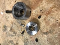
This shows what I believe to be the vise handle. It is marked with the model number of the vise. It fits the bolts fastening the fixed jaw to the base plate, but it does not seem to fit the main clamping screw assembly of the vise:

The end of the clamping screw has a finely machined round recess Ø 30 mm x 14 mm deep, with a single Ø 4 mm cross hole:

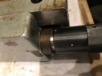
The outer black piece is a sleeve. There is a needle bearing between it and the screw:

I'm thinking the missing part might be an interface between the Ø 30 mm recess and the handle. If I pin the sleeve and the main screw assembly together through the 4 mm hole, I can turn them by hand to close the vise. It seems to clamp, but I am not at all sure if it clamps securely. Furthermore, the needle bearing inside the sleeve confounds me. If the sleeve and the screw were meant to pin together, then what is the purpose of the needle bearing?
I contacted Gressel about a manual for the vise, which they provided. The manual is for a newer variant of the vise, some of whose parts look quite different to me. Below is a link to the manual. (I also asked Gressel about spare parts and jaw availability: They said they no longer provide spare parts for the MHS 125, and that jaws sold for the current model Grefors 125 would fit the MHS 125.)
https://forum.zerspanungsbude.net/download/file.php?id=209591&sid=d0a828acf7212b174d3325741d0662f3
Here is a similar manual:
https://forum.zerspanungsbude.net/download/file.php?id=209344&sid=d0a828acf7212b174d3325741d0662f3
These manuals describe a two-speed clamping system. Fast-ish feed through a screw until the jaws close around the work piece, and then an internal toggle lever to clamp the work securely. The manuals say that the outer, black sleeve would stop turning about a turn before final clamping, even as the handle continues. This seems to indicate that the black sleeve is not meant to be pinned directly to the main screw.
Anyone have a hint on how to proceed to get the vise working?
I have an old crummy milling vise Gressel MHS 125 for which I believe I am missing a part. I was thinking to remake the part, but as I am not familiar with this style of vise, I do not know how said part should look. Here is a picture of the vise:

Here is the nameplate:

This shows what I believe to be the vise handle. It is marked with the model number of the vise. It fits the bolts fastening the fixed jaw to the base plate, but it does not seem to fit the main clamping screw assembly of the vise:

The end of the clamping screw has a finely machined round recess Ø 30 mm x 14 mm deep, with a single Ø 4 mm cross hole:

The outer black piece is a sleeve. There is a needle bearing between it and the screw:

I'm thinking the missing part might be an interface between the Ø 30 mm recess and the handle. If I pin the sleeve and the main screw assembly together through the 4 mm hole, I can turn them by hand to close the vise. It seems to clamp, but I am not at all sure if it clamps securely. Furthermore, the needle bearing inside the sleeve confounds me. If the sleeve and the screw were meant to pin together, then what is the purpose of the needle bearing?
I contacted Gressel about a manual for the vise, which they provided. The manual is for a newer variant of the vise, some of whose parts look quite different to me. Below is a link to the manual. (I also asked Gressel about spare parts and jaw availability: They said they no longer provide spare parts for the MHS 125, and that jaws sold for the current model Grefors 125 would fit the MHS 125.)
https://forum.zerspanungsbude.net/download/file.php?id=209591&sid=d0a828acf7212b174d3325741d0662f3
Here is a similar manual:
https://forum.zerspanungsbude.net/download/file.php?id=209344&sid=d0a828acf7212b174d3325741d0662f3
These manuals describe a two-speed clamping system. Fast-ish feed through a screw until the jaws close around the work piece, and then an internal toggle lever to clamp the work securely. The manuals say that the outer, black sleeve would stop turning about a turn before final clamping, even as the handle continues. This seems to indicate that the black sleeve is not meant to be pinned directly to the main screw.
Anyone have a hint on how to proceed to get the vise working?
Last edited:


