What's new
What's new

Shaft repair on 14" bandsaw - Please Advise

calderp

Aluminum
Joined
Jul 22, 2011
Location
New Orleans
I know this has been covered extensively but I'm feeling a bit overwhelmed by options, would love some advice narrowing them down.

The issue is the output shaft on my Powermatic 143 14" high/low speed gearbox driven bandsaw. I'm turning a new shaft for the idler wheel but because it is driven by the gearbox this is a fairly complicated splined shaft that I don't have the ability to make. The input side and spline are fine but on the output side the bearing has spun and damaged the shaft and there is also serious wear where the 14" cast wheel mounts. This wear is on both the ID of the wheel bore and the OD of the shaft. This is a keyed interface.

The first problem is building the shaft back up to size. Options as I understand it are: braze up shaft and turn back to size (advantage - less heat, disadvantage - weaker repair), MIG or TIG shaft and turn back to size (more heat but stronger repair) or cut the end of the shaft off and weld on new material then turn to size. I do not know what material the shaft is, nor do I have enough experience rebuilding machines to hazard a guess. From what I've been reading and given that this is just a 14" bandsaw I would think that either building up weld or cutting and welding in a new section would be an acceptable repair. My preference is probably for building up weld simply because I don't have any 4140 or similar material on hand to replace the damaged section but if that's a better repair I can certainly get some. If I do weld up and turn back down should I overcut the shaft first so that I'm not turning on the interface between the shaft and the weld metal? Can I mig or tig with mild steel wire/filler?

The second issue, assuming the shaft is brought back to tolerance, is the wallowed out ID on the cast bandsaw wheel. The easiest solution, I think, would be to bore the hub and turn a bronze bushing. Bronze because I will need to cut the keyway into my bushing and that will need to be done either manually with a file or by setting the lathe up as a manual shaper using the carriage (is there another, better way I don't know about? We don't have any broaches or an arbor press anywhere near large enough to fit the 14" wheel).

One question is, if we go with a bronze bushing can someone hazard a guess at reasonable minimum thickness? I would prefer to leave as much of the cast hub and keyway intact as possible. Given this would it be a better idea to make the bushing in steel? If I can make a significantly thinner bushing using steel maybe it's worth the extra effort when cutting the keyway.

Is there a better or easier way to solve this problem? It seems like people really like these taper bore bushings but I don't feel confident in my ability to manually turn a good taper in the bore of the bandsaw wheel.

Any/all advice is appreciated, this is new territory for me. Thanks
 
Some pictures would help immensely. Also helpful would be the amount of wear are we talking about? .010? More?

Classic method is to turn shaft undersize to cleanup, bore hub oversize to cleanup and make a new bushing to fit based on new dimensions. The new bushing can have a flange on it that attaches with a screw or two to the hub, if there's enough meat.

Taperlock is ideal but not for a wheel that doesn't have the beef in the hub to take up the "hoop stress".

Again I'm just throwing out generalities from not being able to see size, scale, or lack of actual dimensions.
 
You did not give the original shaft diameter or pulley bore. But, if it is a standard fractional inch size, you can buy a steel sleeve with a gap for the key. Then you just bore the pulley to the 1/16 or 1/8 inch next larger size and Loctite the sleeve in place. If you doubt the Loctite joint, you can drill for a Dutch key.

https://www.amazon.com/DEWHEL-Adapter-Pulley-Reducer-Bushing/dp/B07ZPX8TD6

You can do the same thing on the shaft, but the shaft will be weaker in proportion to how much you reduce the diameter.

Larry
 
Some photos would be of tremendous help.

For the pulley / shaft interface, I would consider a keyless bushing for this repair - if the cast pulley has enough material around the bore to support the hoop stress of a keyless bushing, this is the easiest, cheapest, fastest repair option.

Keyless Bushings: Browse All Sizes | B-LOC | Fenner Drives

Turn the shaft down to the next standard size whether metric or SAE inch size - then pick a bushing to fit that shaft size from the website above and with an OD that your pulley can safely be bored . . . forget about the keyed interface - not needed with this bushing design.
 
Oh, this is great already. The keyless bushing and gapped sleeve are both new to me. Sorry for the lack of info, I'm at home and just getting started, I should have taken my measurements before I posted. I will try to get to the shop today for measurements and photos. The shaft is in the neighborhood of 1" and wear on both shaft and bushing around 10 thou I believe. Will confirm asap.
 
Whew, this machine is pretty dogged out. Plenty to do.

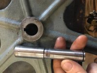
The idler wheel which even I should be able to turn a new shaft for is at .765 with the wheel bore varying between .767 and .773. This shaft presses into a double bearing assembly on one side and into the cast wheel on the other. My inclination for this was to bore the hub as little as possible, say to .765 or .760 and then turn a new shaft to fit. Someone has already been messing around in here as the shaft simply has a flat instead of a keyway while the wheel is keyed. The finish on the shaft makes me think it was shop-made. If I do make a new shaft is there any reason why I couldn't chuck an endmill into the lathe and put the shaft in a toolholder then crossfeed it to mill a keyway? There is not enough material in this hub for a keyless bushing.

idler shaft.jpg

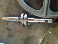
On the drive side I get .750 just above the damaged surface where the bearing spun so I believe that was the original shaft diameter. At the spun bearing I get .745-.747 with a small low spot at .741. At the interface with the cast wheel hub I'm getting a fairly consist .745 +- .001 where I can measure it but there's a lot of damage.
The ID of the cast wheel hub is from .753 to .762. This wheel (drive wheel) is a different casting (not sure if that's original or not) and has plenty of meat in the hub, just over 2" of thick casting. The nearest keyless bushing I can find is 18mm which would only require turning the shaft down to .740 but that requires a 47mm / 1.85" bore diameter which doesn't leave me with much meat in the casting.

shaft damage.jpg
shaft damage 2.jpg
 
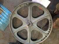
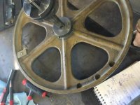
I'm also a little surprised by the balancing that has been done on these wheel. There is a large weight and some deep drilling on both wheels, should this be a major concern?

balancing.jpg

balancing2.jpg
 
Given all the various issues here I think my next move should probably be to check the TIR on these wheels. If I can get away with a very amateur question I'm not really sure how to chuck and indicate them. I suppose I need to chuck onto the rough cast surface on the outside of the 'hub' as there's nothing else really to grab but I'm not actually sure how to indicate the ID due to the keyway. Do I need to cut a piece of stock to fill the keyway so that I'm not catching the indicator probe? This is with a 4-jaw of course.
 
Have the same saw, made the same idler wheel repair. I just turned the buggered up shaft enough to clean it up, mig welded it up, turned it back to size. As far as the bore on the cast iron wheel , I just bored it out and made a bushing from
4140 and shrink fit it in the wheel.
While you at it get a set of Carter’s guides for your saw. Nightvv BBC and day between them and the factory guides.

Oh, great maybe you can help with a couple questions. Do you mind peeking in your saw and telling me if the wheel castings look the same to you as my photos? My wheel castings have some quality control issues - nothing critical but not what I'd expect from powermatic and the output shaft in the gearbox has a metric bearing in it I have a theory that someone rebuilt the saw with some cheap import wheels. You didn't find any metric bearings in there did you? That one has me confused because it's on the output shaft of the gearbox so the OD is a press fit into the gearbox housing.

Anyway I think on the idler side I'll bore the pulley 20 or 30 thou and turn a new shaft to fit since the shaft that's on the machine is missing the pulley keyway anyway.

Drive side I think I'll do what you did on your idler shaft, mig it up and bore the wheel for a bushing. It will be a pain to do the keyways with the mill down but I'll figure it out.

Do you remember what your interference was for the shrink fit? I was concerned about cracking the casting going that route but if it worked for you...

Carter guides were on order before I tore the saw down. Really looking forward to getting it tuned up, it cuts fine as is but it could be so much nicer.
Just seeing this will check when I get home on the wheels, I will say that I do believe that they do have the balancing holes.
I didn't mess with the bearings on my saw or measure them. Being as mine is from the 70's I doubt there is anything metric in it though. Your plan on the idler side sounds fine to me. I just wanted to keep the original dimension for my own reasons. Boring the upper idler wheel was not easy. It took all the capacity of my 4 jaw and there was no good machine surface to indicate from unless you cut off the rubber tire as the bore was wallowed out. what I did was turn a pin that fit into the bore as tight as I could, then threaded it for a nut, and checked the runout on the rubber. It was within a few thousands so I simply held a sanding drum on my Dremel and ground the rubber concentric, and turned a light cut on an exposed part of the wheel I could indicate off of. I then put it in the 4 jaw and bored the hole for my bushing. IIRC I used a barrel stub for the bushing which is 4140 or 4130 ph and .002 thou sounds about right. I think the rule is .001-2 thou per inch of diameter.
On the output side of your drive shaft, another option may be to cut it off, then bore and thread for a repair stub. the advantage of that Is no heat going into the spline to ruin whatever heat treat is there. Ive done this on an electric motor, it works well.
Im in the BR area if you want to make a drive over or need some help.
FYI I bought my saw from a guy that bought it at the Avondale shipyard auction and it still had the Avondale tags. He said there was a bunch of them there. My saw had obviously been tipped over as there weld repairs to the frame and the gearbox was bone dry so check that out before you run it.

Thanks. Sorry for the delay I picked up an arbor press to help with broaching the new keyways but the guy didn't mention until I arrived that it was missing the ratcheting handle so now I'm on another repair. Soon as we get the VFD installed on the mill and the arbor press up and running I think this will be a simple project. I've got a lot of room on the drive shaft to play with so I was going to turn a fat AL bushing as a heatsink and weld very slowly. The splines aren't really load-bearing they're just for engagement of the backgear so I'm not as concerned about temper. Looks like I'll turn a new idler shaft and weld/turn the lower shaft at 20 or 40 thou over (actually a metric dimension for me, since someone has already fitted a metric bearing in there for some reason. Guess it'll be good enough for another half-lifetime of service at the rate we use it, and then the next guy will be even more confused than I am about all the 'modifications'...

I did pull the rubber off the wheels so that we can indicate them in properly. The quality of the casting is so bad that I think they must be imports jammed in at some point to replace the originals so I doubt they're very true to begin with. Suppose I'll get indicated in as close as I can with the 4-jaw on the rough casting then turn a shoulder to grab and flip it over. If they're out badly enough I'll bore the ID as needed and turn a bushing as you've described but if I'm lucky I can get away with just cleaning up the bore and machining the shaft a little oversize to fit

Very much appreciate the advice.

Just make sure the bore and the od are are dead on concentric or your blade will be doing the tight loose tight loose and that never ends well.
 
Just make sure the bore and the od are are dead on concentric or your blade will be doing the tight loose tight loose and that never ends well.

Yep, before I tore it down you could see the blade tensioner stepping up and down about 1/4" as it ran. Especially not fun on the high gear... I got the first one indicated in fairly close last night, I think they might be close enough to concentric that I won't have to do a lot of turning


Back
Top