What's new
What's new

Threaded hole strength in 6061

shorton

Plastic
Joined
Nov 16, 2006
Location
Mid-South
I need to determine the tensile strength for a standard steel M3 socket screw that is threaded into a 6061 aluminum part. Alu threads will be tap-cut. Thread depth is 4.5mm, but I'd say allow .5mm for chamfer, etc., call it 4mm of engagement. I can't make the hole any deeper.

Any engineers or bolt gurus that could show me the math to determine?
 
I don't know how strong an M3 thread is but I do know when I design something, it's usually with a screw that has more than ample strength for the application. I try and keep it 1/4" and up, those little baby screws strip easily and who likes turning miniature wrenches anyway?
 
I'm constrained by the screw size but moreso by the depth of engagement. Bigger screws means fewer threads engaged. I will be using multiple M3's, btu I need to know the strength of 1.

If I did this every day I might could swallow $750 for their software. As is, I just need this one calculation. So $750 is a lot.
 
Not sure if aluminum applies but definitely in steel, the first 7 threads take nearly all the load. This is because of error in the thread pitch when they are manufactured. The bolt stretches under tension and first thread engages and starts to get stressed. More tension is applied and the 2nd begins to take more of the load and so on. After a while catastrophoc failure occurs, and it was shown the returns diminish after 7 threads of engagement.

So for your 4mm of engagement, im getting a pitch of .57mm to get 7 threads engaged. So looks like your on the right path with the M3 thread.

Also, I personally would thread form that size, those taps are easy to break and you'll get a stronger thread in the end.

Edit to add: this wiki article talks about bolts and material being dissimilar metals. Seems pretty relevant.

http://en.m.wikipedia.org/wiki/Bolted_joint
 
Sense the aluminum is the weaker link in the assembly, you should use its properties as the ultimate threshold of strength. The aluminum will fail not the steel bolt. Not sure but my opinion.
 
This can't be that hard to calculate. Let's see...
The screw is far stronger than the female, so the shear diameter will be equal to top diameter (3mm). The theoretical width of the thread should be 7/8P, so 4mm*7/8=3,5mm solid height. So without factoring in tolerances we get a shear area of pi*D*h=33mm^2. If the shear strength is 200MPa (seems high, but that's what my sources tell me) the shear load should be 6600N.
 
I think you can make up some samples and torque wrench them to failure. Use T = 0.2 F * d to get a rough handle on what you are doing there. T = torque, F = fastener load, d = dia although I forget if its major or minor, I would have to look that one up. Also its not an exact equation, its something to get you in the ballpark, a safety factor would then be your friend.
 
It's the nominal major (in this case 3mm). If you do this, make sure to lubricate the thread a bit in order to get better consistency. This will give you the failure point +/-15% fairly reliably. Helicoils and larger diameter fine pitch bolts (not familiar with metric, fine series may not go small enough) will both give you stronger results.
 
If the numbers come out to be enough tensile strength ... Maybe use a better grade of aluminum if you are limited to that size fastener. On the race car parts that are under the most stress, we use 2024. Also the pitch makes a big difference in aluminum, maybe figure out the strength for other pitches.
 
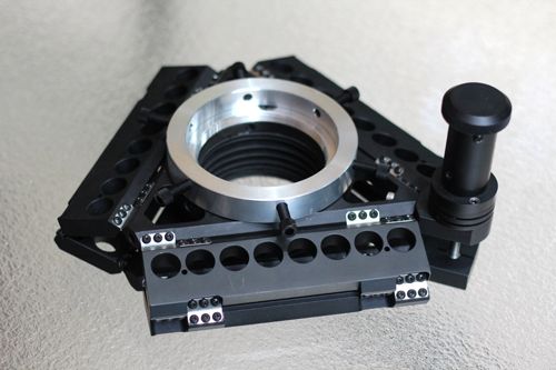
Can't really say about calculations but after producing 10s of thousands of blind 4-40 tapped holes in 6061-T6 I found that a Balax roll tap has worked best for me in terms of strength. I use six black oxide SS 4-40 Philips button head screws to hold each SS flexure in place on my compliant telescope focuser as shown below. BTW there are 18 pairs of SS flexures in each focuser.

Don Clement

 
Don,
Nice application! Can I ask - does the roll tap "upset" the leading edge normal to the hole such that you need to countersink the hole first, or do you need to move the material after perhaps? I've always pondered this about roll-forming; the material must be going somewhere....
 
Don,
Nice application! Can I ask - does the roll tap "upset" the leading edge normal to the hole such that you need to countersink the hole first, or do you need to move the material after perhaps? I've always pondered this about roll-forming; the material must be going somewhere....

I drill and tap these holes on my CNC mill. I start with a spot drill and program the spot drill countersink to account for any material forged or upset by the final operation of using the forming tap. I don't want any material under the flexures to cause the flexures to slip. The whole idea here is the movement is stictionless only if the flexure does not slip.

Don Clement
 
I'll admit I clicked on the thread hoping to see and learn from some really conclusive and technical posts from authorities on this topic, but unfortunately I guess it's just one of those things where nobody /really/ knows what's going on, and practicing engineers just get by with big factors of safety to account for the uncertainty. So I'll throw in my $.02, with the caveat that I don't really know what I'm doing, and am still trying to learn better techniques to analyze bolted joints. (advice on the internet is worth no more than what you paid for it)

The NASA Fastener Design Handbook NASA RP-1228 (http://snebulos.mit.edu/projects/reference/NASA-Generic/NASA-RP-1228.pdf) has some basic equations for estimating fastener pullout strength. See page 21 of the handbook (page 23 of the pdf).

Fulmen's technique of estimating pullout by calculating shear strength of the cylinder of aluminum at the OD of the fastener is a decent way to estimate. It's also what the NASA handbook does, except they include a de-rating of that calculated number by ~50-67%, which matches my experience. I think the number Fulmen came up with is a bit high, likely due to not including the factor of 2 or 3 de-rating. This technique assumes the female thread has significantly less shear strength than the male thread, and assumes the male thread is made of a somewhat stiffer material than the female thread.

If you need more pullout strength and have the room, a helicoil or other threaded insert will get you closer to the breaking strength of the fastener without making deeper threads.

For like-material bolted joints (steel bolt in steel threads, etc), nuts can be used as a rough guide of adequate thread engagement for full bolt strength. Standard nuts are designed to have enough thread engagement that the bolt fails in tension before the nut strips.

If you decide to do a test-assembly, I would recommend measuring thread pullout strength directly with a load-cell or weights rather than using a torque-wrench, due to huge uncertainties in the frictional resistance of bolted joints. I would expect these threads to fail at <800 lbf, considering a 70ksi 6-32 fastener yields at ~650 lbf and a #4-40 goes at ~450 lbf.

Note, it is considered bad design practice to design bolted joints such that the working loads exceed the preload of the fasteners holding the joint together. I wouldn't recommend joint preload beyond ~70% of yield strength, which in this case will likely be driven by thread pullout strength rather than fastener yield strength.

As an aside, Don, that is the most beautiful focuser I've ever seen. Super-cool design and implementation!
 
Thread calculations are nice however there are real world factors that also influence how well screws do in 6061-T6. Over the years I developed a procedure in applying torque to the 4-40 screws in stages. Also the black oxide SS screws used have a oily coating which contributes to the efficacy in 6061-T6. Using used 4-40 screws has a different outcome. Also applying torque at one time does not work as well as applying initial torque, waiting a time period, and applying a final torque. It seems that 6061-T6 has a memory. Sometimes practical engineering experience adds to the calculations.

As an aside, Don, that is the most beautiful focuser I've ever seen. Super-cool design and implementation!
Thanks. I was granted a patent for that design. Last May that model was used on the Palomar Hale 200" at F/3.3 prime focus to autofocus M51. See pics below.

Don Clement


Back
Top