What's new
What's new

Formula for determining Head Tilt for Conical Cutter?

Scottl

Diamond
Joined
Nov 3, 2013
Location
Eastern Massachusetts, USA
I have what I believe is a simple problem but for some reason I am unable to figure the necessary formula required.

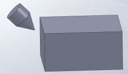
I have to machine a 90° included angle in a piece that has an obstruction at one end that prevents using a 90° cutter in the normal vertical position. There is enough clearance below the obstruction to do this with a 60° cutter with the head tilted to the point where the effective cut will be 90° but I am unable to puzzle out the formula to determine the required head tilt. I can approximate the angle using a 60° gauge, a 90° V-Block, and a protractor but since I would be using only sight to determine when the effective angle was 90° I might be off by a degree or two.

Does anyone know the formula for this?
 
Perhaps a simple explanation might help.

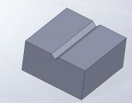
I am machining a V-groove to hold the cutter in a casting for a closed throat router plane. The throat is a hole in the baseplate part with a thin rim that prevents normal end mill access. I machined the other, open throat side with a normal 90° V end mill.

The baseplate is clamped against an angle plate to position the cutter post parallel to the table for milling. I want the router plane cutter to be supported as fully as possible so that is why I do not want to mill the V most of the way and then make a clearance cut below it.

If you stand a triangle on its point with the flat side facing you and then lean the top away the apparent included angle will increase. What I am looking for is the formula to determine the angle of lean to make sixty degrees appear like ninety. Once that angle is known I can lean a sixty degree cutter and mill a ninety degree groove the entire length of the post and through the baseplate. This is a casting so there is no way to mill it and then assemble the parts.

I can photograph the part tonight when home if that illustrates the problem better. From brief fiddling early last night (before Halloween trick or treaters) it looks like the lean required is close to 25 degrees.
 

Yes, photo 4 exactly depicts the operation. I probably could solve it with two different trig operations, one to figure the apparent change in center line height with the same width and two different angles and then figure the tilt from the apparent change in height but I figured there must be a formula as this machining problem probably has come up before.
 
Is it 45 degrees? By my figuring I'm getting 54.7 degrees. I could be way off. They don't let my brain do too much work any more. Damn CNC machines and CAM software get to do most of the thinking. Grumble grumble... Bah humbug
 
Is it 45 degrees? By my figuring I'm getting 54.7 degrees. I could be way off. They don't let my brain do too much work any more. Damn CNC machines and CAM software get to do most of the thinking. Grumble grumble... Bah humbug

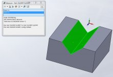
Pic 2 in post #5 shows the angle. I was a little suspicious it came out to 45° exactly.

44° tilt produces a 88.07° angle. 46° tilt produces a 92.07° angle.
 
Is it 45 degrees? By my figuring I'm getting 54.7 degrees. I could be way off. They don't let my brain do too much work any more. Damn CNC machines and CAM software get to do most of the thinking. Grumble grumble... Bah humbug

When I did the double trigonometric approach I got 35.26 degrees from vertical, 54.74 degrees from horizontal so that makes sense.

With angle A as 45 degrees and sides a and b as 10 (arbitrary) I then redo the calculations for thirty degrees with side a still at 10 and get side b (the vertical centerline) as 17.32, or 1.732 times what it was at 45 degrees.

Now to solve for slope I used 17.32 for side c and 10 for side b, resulting in an angle A of 35.26 degrees.

What this represents is:

Side c is the real height of the 60 degree cutter.

Side b is the apparent height when tilted, which must equal the height of the 90 degree cutter when vertical.

Angle A is the tilt from vertical of the cutter axis.

Oh crap, I wound up doing it the long way round anyway. I hate to exercise my brain and if I keep it up I might develop an aversion to Youtube and network TV. Worse yet, I might figure out that zombies can not possibly exist.

Edit: No plans to get a shaper and I only plan to make one of these so even buying a special cutter would not be attractive. This is more of a "retro" project to somewhat back off from my addiction to power tools. I own three routers of various size, not counting the Dremel tool and router attachment.
 
Last edited:
Okay, I figured out what i was doing wrong. I was figuring everything basically as if there was a plane intersecting the center of the cutter, which is not where the cutting is actually happening. Sorry Stephen, I'm not going to be able to 'splain my thinking in any coherent way, but it looks like 45 degrees is correct.
 
Kyle I don't really get from your diagram how you are doing the math. but "assume" a 60° cutter with neutral rake that is only as thick as the cutting edge (flat spade cutter, no actual thickness) Also assume it is 1" wide at the top. to make a 45° trough 1" wide at the top, it has to be leaned over until that width is attained.

So, the 60 cutter is 1" long on a side (sine of 30°) the 45 trough is 1/2" deep at 1" wide by definition. So the length of a side angle down to the bottom, is .70711. Lean the cutter over until the point touches the bottom and the width touches the top. So along the side, the cutter touches 1" of length at .70711 up the side; for a distance along the bottom of .70711. so the sine of that angle is 1/2" (the trough depth) over .70711, the distance to the point, which is the tangent of the lean angle. .5 divided by .70711 = .7071. The arc tan of .7071 is 35.264° including some rounding error. The OP can decide how much to round.

Either that or I really need to go back to school.

:)

smt

Edited: Looks like a whole bunch of us were ciphering at once! At least some of us got the correct answer. And as i was more or less pointing out, either angle is correct depending whether referenced from horizontal or vertical :)
 
I get 35.264°. which oddly is complementary to Frenchy's calculation. So we must be thinking the same way and doing the same thing wrong, more or less??? (My answer plus his answer = 90° split the difference and it's 45° :D )
smt

Maybe I have something wrong. When I model it differently I get you and Frenchy's answer.

Groove 7.JPGGroove 5.JPGGroove 6.JPG
 
Maybe I have something wrong. When I modelView attachment 183433View attachment 183434View attachment 183435 it differently I get you and Frenchy's answer.

In post #13 I admit that my calculations were incorrect. I guess the computer wins. In our calculations we are all assuming that the cutting action is happening on the plane intersecting the center of the cutter. In fact when the cutter is tilted the plane that is actually cutting the geometry is tilted (if that makes any sense). Anyway I agree that it looks like it should be 45 degrees.
 
In our calculations we are all assuming that the cutting action is happening on the plane intersecting the center of the cutter. In fact when the cutter is tilted the plane that is actually cutting the geometry is tilted (if that makes any sense).

It is 45°. Hard to wrap your head around but it is like you said, the cutting profile isn't through the center of the cutter.

Weird thing is, when I model it a third different way I get 44.9876°, not the exact 45° I get from the first method.

Kyle I don't really get from your diagram how you are doing the math.

That would be because I am not doing the math. :D
 
When I did the trig calculations my cutter was imagined as a very thin plane because as the rotating cutter is moved along the mill's X axis it is as if a tool of that shape were scraping modeling clay and creating a ninety degree V.

When I next get a chance to work on it I will mill a piece of scrap first because if different people are getting different results with different methods some results (maybe mine) are wrong and I don't want to spoil a nearly finished piece.

I will update when I get my answer.
 
It is 45°. Hard to wrap your head around but it is like you said, the cutting profile isn't through the center of the cutter.

Trig'ng it out I got ~35.274°, but when I modeled it and added a plane at that angle it had to be from horizontal to make 45°. That was with a 60° included angle sketch.

Revolving the actual shape 180°, so there's a flat face to reference CL of the cutter with, it shows the actual cutting portion is not on CL as I thought.

Makes sense now, as if taken further, if you angled it a full 90°, you'd get a round trough and not a flat surface the CL sketch would suggest.

I have no idea how to calculate this.

Edit:

Worried this actually creates a parabolic shape, I looked up 'conics' and confirmed a plane cutting a cone through it's point creates lines. So we're good there. They define these as 'degenerate conics', so maybe someone with better math skills than me can look into this and come up with a formula, if there is one.


Back
Top