What's new
What's new

A way to set small angles accurately.

andypugh

Plastic
Joined
Mar 29, 2011
Location
Essex, UK
I have a Harrison "Universal" milling machine. where "Universal" means that there are both a horizontal spindle, a pivoting vertical spindle and a swinging table.
The swinging table means that the machine can easily be set up for hobbing gears with spiral gear hobs.
Each hob has a lead angle engraved on it that tells me how far the table needs to be swung.
But the angles are typically something like 1°45' and the graduations on my table are every 1 degree and are fairly hard to see.

So I had the idea of using a micrometer head to dial in the angle. For small angles a 1mm micrometer at a distance of 57.29mm from the pivot moves the table 1 degree for every 1mm travel. ( 57.29 is calculated from 1/tan(1) ). An imperial micrometer head could be used at a distance of 5.729" from the pivot. Then it would, of course, be 1 degree for every 0.1" marking on the micrometer.

The problem is that this ceases to be accurate as the angles increase.

So I had the idea of having the micrometer bear on a specially shaped ramp that to correct for the disparity as the table swings:

IMG_5194.jpg

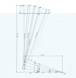
The construction for the shape of the cam is shown below. It will be a different shape for every machine, as the distance from pivot to the micrometer face affects the profile.
The 0 degree line is constructed to put the end of the ramp in the right place for the other part dimensions. Then a similar construction is made at 5 degrres, and with a 5mm shorter construction line. This is repeated for a few angles.
The points can then be joined with a spline, and a CNC machine makes making the special shape fairly easy.
Screenshot 2020-04-12 at 22.53.34.jpg
 
1 inch travel indicator clamped to tool holder and run against side of table or work piece. For. Instance .025 for 1 inch travel of table.
 
That works for a lathe. For this style of mill, where the axis itself swings, there isn't much to indicate to. There is the flat section of the column between the double V ways, but there is no reason to trust that as a reference face.
It's an odd thing, the swinging X axis. It really doesn't change much. I guess you can cut an X pass and then a Y that is not at 90 degrees.
But I think that the main application was meant to be cutting spiral grooves using the horizontal spindle and gearing a rotary head to the X feed.
 
I am sure your method can work, but it seems to involve a ramp that must be custom made for your machine.

Back in Jan-Feb 2009 I had an article published in the Home Shop Machinist titled, "Setting Up Accurate Angles - Inexpensively". I worked out the method when I needed to turn and grind a taper for a collet holder on my lathe. It uses a fairly inexpensive set of angle blocks that allow you to assemble them to any whole number of degrees and I added a technique that uses the same principle as the sine bar to obtain any angle between those whole numbers. It does have some approximations in it, but for distances like 5 or 6 inches, they are small enough to be completely ignored. I do discuss the errors and their magnitude in the article. Generally we are talking about +/- 1 minute and that does not increase with larger angles. The cost of the angle block set is probably your only expense as the other required tools and materials (drill bits or pins, ruler, a dab of model clay) are present in almost every shop. That back issue is still available from Village Press for $6.50:

HSM Vol. 28 No. 01 Jan-Feb 2009 << Back Issues << The Home Shop Machinist << Metalworking << Storefront << Village Press

Or you can obtain that article here for only $2.00 with an instant download:

Using Angle Gauges for Any Angle - HomemadeTools.net

Although math is used, I provide an Excel table and you only need to use addition and subtraction with the values from it. If you don't have Excel, then any scientific calculator would serve.
 
how do you make that cam?

When I set angles with a TDI or sensitive indicator, I usually work to .001 over several inches.

Getting .001 on a mic head and a cam block appears to me to be like pushing a chain up hill.
How was the cam produced? How did you come to accept it's accuracy?
 
You can't tram the angle because you are turning the axis of travel. You can tram the complement to the angle using the saddle.
 
If you lack jo blocks/slip gauges, work out the stack height and turn two buttons, no1 any convenient size, no2 same plus the stack height FOR the centre distance, 10” is good, or look up setting heights for a 10” sine table
Mark
 
how do you make that cam?

Using the milling machine, which has been converted to CNC.

My machining of the idea is probably imperfect, though good enough for my home-shop requirements.

But when modelled with 3D CAD it works perfectly. I was describing the technique, rather than showing off my implementation.
 
Hobs aren't that picky about the setting angle ... just sayin' ...


It's true.

Years ago I agonized over getting the angle perfectly spot on. Even made a sine attachment for a Hobbing machine swivel so that I could dial it in to a few seconds of accuracy. And then I performed a metric buttload ( that's an ISO standard ;) ) of experiments, gathering empirical data on what happened with each measure of inaccuracy in swivel angle setting.

Learned quite a bit doing those. And the sine attachment that I spent so much time designing, making, and installing was removed and put on the shelf.

Funny thing was that using the Hob, the swivel angle only affects one minor aspect of the result. But sharpening the Hob, that angle is critical, as it will affect the actual, resulting Involute Form.
 
Accurately setting the angle.

I have a Harrison "Universal" milling machine. where "Universal" means that there are both a horizontal spindle, a pivoting vertical spindle and a swinging table.
The swinging table means that the machine can easily be set up for hobbing gears with spiral gear hobs.
Each hob has a lead angle engraved on it that tells me how far the table needs to be swung.
But the angles are typically something like 1°45' and the graduations on my table are every 1 degree and are fairly hard to see.

So I had the idea of using a micrometer head to dial in the angle. For small angles a 1mm micrometer at a distance of 57.29mm from the pivot moves the table 1 degree for every 1mm travel. ( 57.29 is calculated from 1/tan(1) ). An imperial micrometer head could be used at a distance of 5.729" from the pivot. Then it would, of course, be 1 degree for every 0.1" marking on the micrometer.

The problem is that this ceases to be accurate as the angles increase.

So I had the idea of having the micrometer bear on a specially shaped ramp that to correct for the disparity as the table swings:

View attachment 284758

The construction for the shape of the cam is shown below. It will be a different shape for every machine, as the distance from pivot to the micrometer face affects the profile.
The 0 degree line is constructed to put the end of the ramp in the right place for the other part dimensions. Then a similar construction is made at 5 degrres, and with a 5mm shorter construction line. This is repeated for a few angles.
The points can then be joined with a spline, and a CNC machine makes making the special shape fairly easy.

View attachment 284759
If distance from the pivot is set 10" to the micrometer; we can look up the sine for the angle we need to set. Multiply by the sine x 10" and we have the angle needed accurately. The same as using 10" sine bar.

Best Wishes
Roger
 
I have a Harrison "Universal" milling machine. where "Universal" means that there are both a horizontal spindle, a pivoting vertical spindle and a swinging table.
The swinging table means that the machine can easily be set up for hobbing gears with spiral gear hobs.
Each hob has a lead angle engraved on it that tells me how far the table needs to be swung.
But the angles are typically something like 1°45' and the graduations on my table are every 1 degree and are fairly hard to see.

So I had the idea of using a micrometer head to dial in the angle. For small angles a 1mm micrometer at a distance of 57.29mm from the pivot moves the table 1 degree for every 1mm travel. ( 57.29 is calculated from 1/tan(1) ). An imperial micrometer head could be used at a distance of 5.729" from the pivot. Then it would, of course, be 1 degree for every 0.1" marking on the micrometer.

The problem is that this ceases to be accurate as the angles increase.

So I had the idea of having the micrometer bear on a specially shaped ramp that to correct for the disparity as the table swings:

View attachment 284758

The construction for the shape of the cam is shown below. It will be a different shape for every machine, as the distance from pivot to the micrometer face affects the profile.
The 0 degree line is constructed to put the end of the ramp in the right place for the other part dimensions. Then a similar construction is made at 5 degrres, and with a 5mm shorter construction line. This is repeated for a few angles.
The points can then be joined with a spline, and a CNC machine makes making the special shape fairly easy.

View attachment 284759

There are 2 problems you are fighting here:
1. Small Angle Approximation. For small angles Tan(A)=A in radians. This is why the correlation of distance to the angle is linear. For larger angles you need to make a table correlating displacement to the angle calculated from TAN values of the angle.
2. The second problem is the the flat face of micrometer and changing length of the hypotenuse to the point of contact. You can reduce this effect by using a ball shaped tip on the micrometer, Kind of like what you are doing with the curved part you made, but you won't eliminate it completely.

You can overcome all these issues by creating a look-up table for the non-linear correlation between micrometer setting and the angle.


Back
Top