What's new
What's new

Wiring a 9 lead motor to Drum Switch

projectnut

Stainless
Joined
Mar 4, 2006
Location
Wisconsin
I know this subject has been discussed several times in the past. However I can't find a diagram that matches the particular motor and switch I am trying to configure.

The motor is a Marathon 120/240 volt, single phase, 1 hp, reversible. The drum switch is a Relay and Controls Corp. RS-1. I have attached picture of the wiring diagram as it appears inside the switch cover

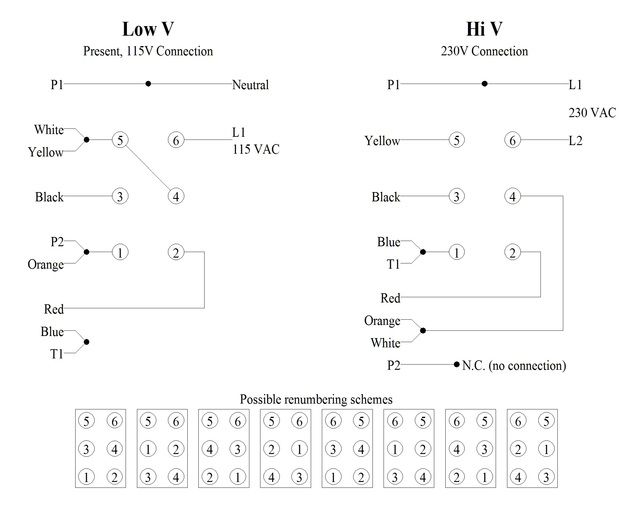
In this case the motor has manual a overload and 9 wires. According to the wiring diagram when wiring the motor to 220 volts 8 of the 9 need to be connected to the switch. The 9th wire is insulated and left unconnected. I am providing a link to the wiring diagram at the Marathon website since the pdf file is too large to post as an attachment

I have been running this motor and switch combination in the low voltage mode for nearly 20 years. I recently installed several 220 volt single phase circuits and would like to switch the motor to the higher voltage.
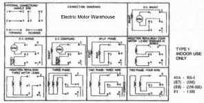
RS1_diagram.jpg

Motor Wiring Diagram:
http://www.marathonelectric.com/CnxDocRequest/PublishedPDF/102005_52_52390_365.pdf

Any help would be appreciated.
 
OWO!! 128 views and no one has run into a similar situation. I have to say I'm a bit surprised to say the least. I thought this was a pretty common motor/switch combination.
 
This is how I did it. The numbers on the leads are for wiring reference only, they don't relate to motor manufacturer designations.
In this diagram below, the overtemp protection was a click switch.

wire.jpg
 
1Φ Dual Volt Motor, Reversible, Thermally Protected, With Drum Switch, Connected for Hi Volt Operation.
1PhaseDualVoltReverse230V AB Switch.jpg

SAF Ω
 
This appears to work but it does not utilize the motor manufacturer's recommended connection scheme. It does not appear to produce any smoke so it should be fairly safe to try. If you do use it, please notice that this diagram does not use the same terminal numbers as the reference provided by the OP. If you use the OP's switch, the numbers must be translated to match.

As noted on the drawing, it does not provide complete isolation from line Voltages. But then, as I and others have already stated, that does not seem to be possible with this combination of motor and drum switch.

Given the choice I would use the connection that I showed above as it does use the manufacturer's recommended connections. Just to be on the safe side.


1Φ Dual Volt Motor, Reversible, Thermally Protected, With Drum Switch, Connected for Hi Volt Operation.
View attachment 197659

SAF Ω
 
Maybe I'm missing something, but all the diagrams I've seen so far have either 6 or 7 leads coming from the motor. On this motor there are 9 leads.

They are:

Black
Red
Blue (2)
White
P1
P2
Orange
Yellow


I do not believe this motor wiring complies with the standard color codes. There are 2 blue wires. One is marked T1 while the other has no markings. There are also 2 black wires. One is marked P2 and the other has no markings. According to the wiring standards P2 should be Brown. The 9 leads do not include the Green physical ground.
 
Here's a modified diagram from the one given above, tailored to your specific motor.

The difference is in the wiring to the thermal protector. In the prior submittal, T1&P3 were shown spliced internally, as some manufacturers do. On your model they need to be spliced externally. All leads are brought out to the terminal box.

As to color and label standards, the lead colors for the 3 windings are standard. They match with the prior drawing and the Marathon drawing. What is not standard is the colors, labels and connections for the thermal protector, each manufacturer uses a different configuration, there is no common standard on this part.

On the wires that have labels,(T1,P1,P2) the labels take precedence over the colors, where you have duplicate colors.

To change rotation, interchange start winding leads, RED & BLK (T5,T8)

For clarification, the other contributors drawings posted have a different switch than the one you posted. EPAIII's was out to lunch...at least I didn't see one.

"Originally Posted by EPAIII,
Given the choice I would use the connection that I showed above as it does use the manufacturer's recommended connections. Just to be on the safe side.

SAF Ω

Marathon 1Φ DualVoltRevTP 230V.jpg
 
Forgive me for not noticing that you posted this question on another board when I posted my previous reply here. I should have noticed as you said there that it was a multiple post.

Anyway, I posted this diagram there:


Like other suggestions here and there, it does not use all nine of the wires in either the Lo or Hi Voltage hookups. This is from the manufacturer's hookup diagram that you posted from the motor's data sheet. If you look at those manufacturer's suggested hookup diagrams you will see that one or more of the wires are not brought out of the motor in each of the wiring schemes. In the Lo V scheme, the blue and T1 wires are simply tied together. In the Hi V scheme the P2 wire is not used at all and MUST be insulated from accidental contact with anything else, including the motor's frame. A wire nut or piece of electrical tape should be used for this.

I have looked at some of the other schemes that have been proposed and, as I commented above, at least one of them looks like it would work. I did not examine RJ's scheme because it uses a different switch and you said you wanted to use your existing drum switch. It may work, I don't know. However, it does share the problem(?) of not isolating the motor from both sides of the 230 V line, even in a center Off position. He has L2 connected to T2 and T4 at all times so those coils are always hot in his scheme.

Motors like this have a multitude of wires to allow a number of possible connections for different purposes. This motor has completely separate connections for the protection circuit and the starting winding. That accounts for five of those nine wires. The other four are simply the two Run coils. Only the four Run connections are actually needed for the motor to actually run. An external start mechanism (rope around a pulley?) would be needed to start it, but those four coil connections would allow it to run. The start coil and circuit uses two more and most people would elect to use it so the motor does not require an external starting device. The thermal protection circuit is also on separate wires. You could leave it disconnected and the motor would start and run and could produce full power. But if it stalled, it might burn up. By bringing these parts of the motor's construction out on separate wires, the manufacturer provides a maximum amount of flexibility in it's use. For instance, additional control or protection circuits could be incorporated BY A COMPETENT ENGINEER: all the connections for that option would be available on those nine wires.

You have at least two workable circuits here in this thread and at least one (mine) on the other board. Don't worry about those "extra" wires. Just connect or insulate them as shown on the diagrams or at least on mine.


Maybe I'm missing something, but all the diagrams I've seen so far have either 6 or 7 leads coming from the motor. On this motor there are 9 leads.

They are:

Black
Red
Blue (2)
White
P1
P2
Orange
Yellow


I do not believe this motor wiring complies with the standard color codes. There are 2 blue wires. One is marked T1 while the other has no markings. There are also 2 black wires. One is marked P2 and the other has no markings. According to the wiring standards P2 should be Brown. The 9 leads do not include the Green physical ground.


Back
Top