What's new
What's new

AT/ATX to 1998 Haas VF-OE Power Supply substitute.

Tryhard

Aluminum
Joined
Oct 26, 2019
Pulled this from an older thread to make its own topic...

...if indeed the power supply is the problem. you can buy a AT or ATX computer unit and the hardest part will be mounting it. I can walk you through the wiring if it needs done. if you look above the most left circuit breaker you will see 2 cables that are from the power supply. the AT or ATX needs the same 2 connector. most do but I was surprised 1 time by a odd power supply that didn't and had to splice the wires to use the original style connectors.

Is there a particular brand or model of AT or ATX power supply that utilizes same connectors or works the best?
Anything that will be more plug-n-play than others?
 
no but I ha e noticed the earlier models have the right connectors. I was at a shop a few months back who purchased 1 new recently. we had to splice the old connections to the new power as they had different ends then the older models like Haas originally used.
 
Look up ATX power supply in Wikipedia or elsewhere. You need the four pin Molex connectors. You also have to jumper pin 14 on the 20 pin MiniFit Jr. connector to turn the power supply on.


atxpinout.jpg
 
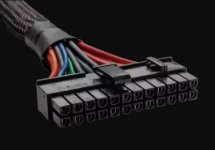
Yeah, there are 2 main-power connectors out there if I recall. My 98 VF/4 has the 24pin type. The one above is a 20pin diagram. There are many links and images out there. We'll get ya going.
AT-PSConnector.jpg
 
Haas LVPS to ATX PSU. Modular?

Yeah, there are 2 main-power connectors out there if I recall. My 98 VF/4 has the 24pin type. The one above is a 20pin diagram. There are many links and images out there. We'll get ya going.
View attachment 273821


Still trying to wrap my head around what all is involved. Confused about if the connectors themselves are used or what. Does it utilize the 4-pin type molex connectors too?
Mine is a 98 VF also, looks like my LVPS was replaced at some point, but our boards are probably close if not same. Were you able to find a modular power supply that is close to plug-n-play? (see pics) Or are the pinouts NOT actually compatible from ATX to Haas?

My power supply itself (see pic) looks like it has a 24-pin female PC main motherboard type connector. Not exactly sure what is on the other end on the Haas CPU board. Same connector on both ends?
Or would a plug from a non-modular 24-pin PSU just snap in place on the Haas CPU board end?
What I'm wondering is if I could find a modular 24-pin PSU and replace with little to no wire modding? That way I just buy a couple and keep em in stock.

Thanks!


a.jpg

Capture.jpg

AB.jpg
 
that moles connector is not used with the ATX type power supply. what you ha e now is a upgraded power supply. have you determined it to be bad ot your issue, before we get into this to far ? if so you to do the ATX will need 1 additional power supply for your driver logic. unless you have the updated drives. if you have the updated drives you will not need the additional power supply.
 
that moles connector is not used with the ATX type power supply. what you ha e now is a upgraded power supply. have you determined it to be bad ot your issue, before we get into this to far ? if so you to do the ATX will need 1 additional power supply for your driver logic. unless you have the updated drives. if you have the updated drives you will not need the additional power supply.

Hoss, I'm only trying to do some research on it in advance. Hoping it will hold up for a while. Still have the machine apart from other repairs. Will get it back together and operational before I "fix" anything else.

Responses from a previous thread of mine on here led me to believe that my power supply needed to be replaced at some point.
(Machine only fully boots when I turn it ON-OFF-ON)

Yes, all (4) X,Y,Z & A drives are new style. Mfgd 9/18.
 
My son is up this week. We are working on the shop. I’ll post a short video on you tube of my innards and pm you the link a bit later.
 
OK- I did a short Vid and posted. Sent you the PM w/ the URL. Hope it helps-
A little commentary- I know where Hoss710 is coming from. He's been a keen resource here for many of us haas-newbs. Since your rebuilding- and these lowe volt PS's can cause numerous issues- My 3cents on a machine your rebuilding is to replace it. but- when it makes sense. if you're not done diagnosing and troubleshooting- you may introduce something new to your woes. But- overall, a clean and new LV PS is warranted once you want to actually use it reliably.


My son is up this week. We are working on the shop. I’ll post a short video on you tube of my innards and pm you the link a bit later.
 
Countryguy, I have an 2005 sl20 with the same Condor SP1730 power supply that fried from a bad transistor. What is the process to use an ATX power supply to temporairly diagnose?
 
Hi,
well.... What's is doing that you may want this as temorary to diagnose>

Note: You will need to go with either an AT style or ATX style. I prefer the AT style. 500W. 400 Min. But either will work. The VF I have runs w/ 5VDC , 12VDC, and -12Vdc.

I did a LOT of LV power supply work in the 90s. About every combination was out there. Condor is a big name. You can possibly even find NOS on that exact PS. (power supply) But probably w/o the custom Haas Connector. then you would just convert/move from old to better (potentially).

Soooooo The first step is to get in there an examine. Find all the lines that come off the condor PS. only those that come off the PS. Not the distribution board.
I usually stick draw stuff. Connector X - 5V and GND line. Connector Y 5V 12V and GND lines. Main dist. connector. multiple 5V and Gnd lines. 2- +12V lines. Large connector. Etc...

Just get in and get familiar. See what wires are 5V ,(red usually) 12V Yellow often. -12V White, GND, black) etc. there is white silk-screen writing on the dist. board which clearly show the pin voltages. You'll see the color of the wires from those.

At this point you can either find the specific Haas power connector (noted in threads here) and rewire an AT or ATX supply to that connector. You'll cut all the needed wires to length off the AT/ATX. strip them and put on the molex (or other) pins. they slide in and latch in to the connector. Then cut-in/splice any other smaller 3 or 4 wires once. I think 2 plug over in the dist. board. ( think there are 2 others besides the 2row 20 pin? I cannot recall).

OR- like I did,
Just mapped out wires from the AT supply to each bundle from the old supply - and cut out and splice. Harbor Freight sells a nice little heat-shrink kit. a few bucks. 2" length tubes in diff. Diam. sizes. worked well. Western-union splice, solder it too, then slide heat shrink over... heat gun it... done. Move on to next. Took an hour or so I think. loosely taped the bundles back.

My advice: Take your time. Map out all the wires before you ever even cut one. To do this, I just stuck the AT supply in and tie wraped it to the frame ,hold it near the old one. and mapped the bundles. I think you'll find that the 12 and -12 may be a different color depending on the PS. AT and ATX I think do not use yellow/white on 12/-12??? google it and it'll show you the pin out and colors. They are standard. (typically). You will NOT need to use all the wires off the AT/ATX. There were a few 5V and GND's if I recall.


Ping back.. I'll watch the thread. Why I take my time... Map something wrong and these boards are so rare- Who wants to fry something due to not taking the time to map it all out... ya know?

final thought- Either way is a bit off from 'temporary' Put the AT/ATX in and leave is is my opinion.


Reference info and some option thoughts:
There are so many power options from Condor There is a model # someplace on it. Could go that route?
https://www.ebay.com/sch/i.html?_fr...tleDesc=0&_osacat=0&_odkw=condor+power+supply


ATX - AT What's the diff?
https://www.techwalla.com/articles/differences-between-at-atx-power-supplies


POWER CONNECTOR CONVERTER. (needs to be researched)
Hmmm Never noticed this one.
Amazon.com: AYA 7" (7-Inch) ATX 20-Pin to at P8+P9 6-Pin with Push Power Button Wires Converter Adapter : Electronics

Countryguy, did the new power supply solve the power on/off/on issue?

I didn't see this directly answered in the thread, and I am curious if you resolved the problem.
 
Hi all; This was 'tryhards' issue w/ the on/off/on. He's still doing the on/off/on shuffle :-) if this is your issue the electrical diagrams in the rear of the manuals show the relay-logic and diagrams. Contactor pulls in, 3 Phase rolls around. The PDU board also sends 1 of the phases over as 110 Vac to the Power supply input. There are some fuses on that PDU for the line if I recall. I do not recall any contactor on that but ... models and PDU's vary. For those reading these and a little queasy on AC that can curl hair some; I do love my fluke (and or HF meter) with High and Low recording. Meaning, I put the clips onto the AC side into the LV power supply. You set to record ... and press the On button. It'll monitor and record if the 110AC even made it there. etc. There are interlocks and such around. Again, the back of the manual in the electrical overview section has some great diagrams.
 
Hi all; This was 'tryhards' issue w/ the on/off/on. He's still doing the on/off/on shuffle :-) if this is your issue the electrical diagrams in the rear of the manuals show the relay-logic and diagrams. Contactor pulls in, 3 Phase rolls around. The PDU board also sends 1 of the phases over as 110 Vac to the Power supply input. There are some fuses on that PDU for the line if I recall. I do not recall any contactor on that but ... models and PDU's vary. For those reading these and a little queasy on AC that can curl hair some; I do love my fluke (and or HF meter) with High and Low recording. Meaning, I put the clips onto the AC side into the LV power supply. You set to record ... and press the On button. It'll monitor and record if the 110AC even made it there. etc. There are interlocks and such around. Again, the back of the manual in the electrical overview section has some great diagrams.
Hi Countryguy, I know this is an old thread, my 01 mini mill has been shutting off randomly, the servo fans continue to run but the 5v and 12v lights on the board are off, when I cycle the power everything comes on and runs normally but eventually the machine will do it again, I noticed it has what appears to be an AT low voltage power supply that came originally (has a Haas pn on it), I'm trying to find a replacement, most are 300 watt (I see you mentioned 400 min) can you direct me to a source for 500/400 watt units?
Thanks in advance, this thread is very helpful
 
err...

good idea to verify which version of ATX the power supply you are replacing is.
the standard was always a moving target and I'm not talking about the pinouts and connectors
the amp ratings per rail shifted dramatically adding more and more to the +12v as more power was required and on board voltage regulation shifted
 
Hi Countryguy, I know this is an old thread, my 01 mini mill has been shutting off randomly, the servo fans continue to run but the 5v and 12v lights on the board are off, when I cycle the power everything comes on and runs normally but eventually the machine will do it again, I noticed it has what appears to be an AT low voltage power supply that came originally (has a Haas pn on it), I'm trying to find a replacement, most are 300 watt (I see you mentioned 400 min) can you direct me to a source for 500/400 watt units?
Thanks in advance, this thread is very helpful
Hey Ho all. gme. welcome to the forum. Here is the one I purchased last. It's installed and running in mine.

The line that feeds the lv power-supply comes of the PDU and from one of the phases looped to that PDU board. It's pretty well labeled. I've posted some other concepts in threads about the diagnosing and debugging I've used from time to time. One of may favs is the HF or other fluke type meter with a voltage min/max monitor. My fluke beeps. Not sure if my harbor freight one does. anyway- Monitor the AC in on that phase possibly. Then setup your meter to watch the DC 5V. Set to min... it'll list the lowest reading. if it goes lower.. then it will change the display to that level. No matter what it bounces back to. See what's going on there possibly? Check your lugs and screws from the AC input , to CB1, to the lower transformer hookups. Then from the bottom of the Xformer too. I have found sooooo many screws that were as loose as my ducks arse. My 3 cents. Swap it out sure, but if it continues- Something else is going on. Semi-conductors and things like IC's, pneumatics, and actuators and motors and other power-components do sometimes act odd and can intermittently short momentarily. May not blow a fuse. May not hit low ohms but they'll mess w/ the AC line used for inputs to other systems. (like a LV power suppy)- and poof... things drop out and you cascade into darkness. Usually simple enough and just swapping prob solves your issue- But we've seen how some of these systems get possessed w/ evil in there bones for us. They know it's to get that one job done you needed out yesterday. If you listen carefully, sometimes you'll hear their laugh echoing around inside the doors. (yeha.. been a day here! lol. went with some fiction too).
 
  • Like
Reactions: gme
Update: I purchased the 400 watt at power supply recommended by Country Guy, I had to splice the power input connector from the factory 200 watt unit on to the new one, the 6 pin connectors needed no modification, a couple of the wire colors differed from the original but checking the voltages on each unit while on the bench before installation verified they were the same, it's been 2 weeks with no shut downs, hopefully this will be some help to someone in the future, thanks for the help!


Back
Top