What's new
What's new

mini mill out of square after Z plunge crash

nccknives

Plastic
Joined
Aug 19, 2013
Location
brooklyn ny
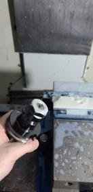
hey guys so I got a second mini mill 01 last month and its been making great parts up until yesterday when I crashed it by plunging it in rapids right into my part due to odd settings from the previous owner causing my offsets to be off by .48. unfortunately something in the head had shifted after. I rechecked my z offset and noticed that everything was .0195 higher then prior. I'm assuming that the linear bearing rails must have sliped from the crash but everything still ran fine including tool changes after I reset my tool offsets. the only thing off was the floor finish of the part. I then switched out the part for a 4x6 pallet to try faceing with a 3" facemill to find it leaving a horrible dished finish when moving in x and a huge step over when cutting in Y. From what I cant tell the head is now tilted to the left and not just by a few tenths but a decent amount. I wont know until Monday exactly how much the step was but id guess a couple thou so simply shimming the spindle doesn't seem like the fix here. I was told I may have to block the spindle then loosen the linear bearing bolts and possibly shift the whole head slightly before retightening them. I did plan on calling in a tech but figured id try something before calling in the tech. Any advice would be appreciated as the mill was perfectly square prior. I included a picture of the crash and the test face i did, you can visually and physically see the substantial step.
WhatsApp Image 2020-11-15 at 1.35.03 AM.jpg
WhatsApp Image 2020-11-15 at 1.34.45 AM.jpg
WhatsApp Image 2020-11-15 at 1.34.45 AM (1).jpg
 
Before you do anything, double check the four floor pads to ensure they've got relatively equal load on them (at least, the two rear and two front should be close). This is to ensure no twist error is baked in. Then use a precision level to check that the table is flat to the bubble, map it with the table forward in Y and all the way back in Y.

If you see a variation you may need to purposely shift the pads to twist the machine to square to the Y linear rails (not a good thing if you have to do this, but...).

Once that's done, find a precision right-angle block. What's ideal is a granite square of A or AA grade, but a good ground cast iron angle will work too, as long as one face is flat and it sits without rocking on the table.

Clean off and lightly stone the table to remove any stuck chips or bumps, then set the square in roughly the middle. Then, using a .0001" test indicator, sweep the Z in by running the head up and down at least 6".

Be careful not to whack any head parts against the angle!

This will help you determine if the spindle itself is off in the Z housing, or the Z housing has moved relative to the Z rails. Make sure to rotate the angle 90* for each of the major axis lines (X-, Y-, X+, Y+), map the readings on paper as you go up and down in Z.

After you've done this (or before, doesn't matter), use the indicator on an arm in the spinde to take a sweep on the table with around a 4-5" radius, and map the errors on a sheet of paper.

These two sets of readings should help pinpoint where the errors lie, once you've gotten them come back with the values for further suggestions.

This is just one approach, others may have better ideas.
 
first thing Monday morning is to take the indicator and swipe the fixture to checkout that step. then take of the vise to clean and check the table in a 6" circle to get a idea of how much its actually off. machine was leveled 6 weeks ago and checked last week for floor sag I don't thick it moved but ill check that as well. best Square thing i can get other then a 123 block is a steel jaw that I can resurface grind to try Monday.


in this case id be fitting the magnetic block on the spindle or in the spindle and swiping the block sitting on the table
"Clean off and lightly stone the table to remove any stuck chips or bumps, then set the square in roughly the middle. Then, using a .0001" test indicator, sweep the Z in by running the head up and down at least 6"
 
the other information I read wasn't about adjusting the z rails but replacing them. it spoke about alignment which I kinda understood but not fully from the diagrams. I figured it may make more sense once I take off the cover.
Linear Scale - Z-Axis - Replacement - Jan 1997
I also read some more info in other threads but it wasn't that helpful it just pointed me in the direction of believing it was a torqued rail.
 
So unfortunately its not looking great I swept the 8" circle and its
+x.0045,
+y.000
-x.0011
+y.0018

And the facemill stepover is .0015
 
It sounds like you were traveling in the X direction when it crashed for how the head is off. My guess is the head twisted on the blocks, I have seen this often on linear way machines. The rails are far better located and bolted to the machine than the blocks. The solution, IMO in front of my computer, is to loosen the 4 bolts on each block and clamp the locating two so they are tight against their reference surfaces on the head then torque them all down to the correct values. DO NOT GUESS THIS, the proper torque is going to be far less than you expect. After doing this you will understand how easy it is to twist the head in a crash. Now see if it is straight, if not repeat but shim one of the blocks to get it straight. Don't worry about shims being a hack, it's normal to adjust the blocks to get things to line up. Once it is all straight then loosen the ball nut and then torque tight.

A big issue with a twisted head is the nut is out of position and alignment with the head casting so you need to get it all aligned before trying to use it.

To fix the alignment in the Y direction, as long as the spindle is parallel with the Z-axis travel, then play with the back two leveling bolts, which is what they are for. I am assuming it sits on 6 leveling pads?

I forgot to mention you may need to make the "clamps" used to hold the blocks tight to the casting. Mine were two aluminum plates with 4 holes. I bolted the plates to the head and screwed two bolts through it pressing on the ends of the blocks. Make sure you know how you're going to do it before disabling the machine in case you need to make them first.
 
If I remember correctly, the Mini Mills are made with steel fabrications and four feet. They're pretty stiff, and it may require shimming the spindle to cheat it square in Y, unless it's so bad that you have to consider worse options like scraping the vertical rail mounts. Ugh...

I think the OP will wind up loosening and fiddling with the Z bearing blocks and re-sweeping the table to best available results.
 
Just got off the phone with Ed my tech at allendale. Now that the cover is off he said to pretty much exactly do that. I was in full rapid plunging in Z. The torque value is 50lb for if the bolts are m10 and 100lb if there m12.


Back
Top