What's new
What's new

Need wiring information on Haas servo controller

9100

Diamond
Joined
Nov 1, 2004
Location
Webster Groves, MO
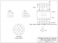
My customer recently had the motor repaired for a Haas indexing table, AKA 4th axis. The encoder has a D9 connector. The connector from the controller had been inepertly reconnected and one wire was broken, so I redid it. I wrote down the color of each wire as I disconnected it and am reasonably sure they are correct but the controller gives error signals. I would like the confirm them but do not have any documentation and Haas is no help. The controller is simply labeled "Servo Controller" with no model number, only a serial number, 3398. Does anyone have a schematic or can take a picture of the wires?

Bill
 
I'll look tonight to see what I have on the black boxes. do you have the manual ? some of the early 1s had the pinouts in the back.
 
Here are some pictures under less than ideal conditions. The connector is the D9 with the shrink sleeving unshrunk is the one in question.

PM has a mind of its own about picture placement, but they convey the information.

I have the user's manual and pin connections on the round AN connector but not the one to the encoder.

Bill

IMG_2976.jpg
 

Attachments

  • IMG_2981.jpg
    IMG_2981.jpg
    54.6 KB · Views: 121
  • IMG_2977.jpg
    IMG_2977.jpg
    48.3 KB · Views: 104
I'll look tonight to see what I have on the black boxes. do you have the manual ? some of the early 1s had the pinouts in the back.

If you happen to run across any info on the Red units- Kid and I have a TRT210... so the 210 and 160? mashed together. if you happen to see anything- We're in the dark here as well on this should it go down.

I know there are white, red, black, silver- Would love to know the nGen order on these. 1st gen, 2nd gen, etc by color. Always wondered that one.
 
The encoder usually has eight wires, Vcc, Gnd, A+, A-, B+, B-, Index+, Index-.
Do you have a picture of where the other end of the DB9 connector goes in the box? Typically something like a 26LS32 quad 422 line receiver.
The female side of the DB9 does not look in good shape, you might consider replacing the set.

The wires go into a junction box for the large cable with the round AN style connector. We should have a diagram of the pinouts on that connector but no one knows where it is. If that shows the pinouts on the other end, I could ring them and see an error.

The DB9 is in good enough shape, I don't think that is the problem.

Bill
 
If your round AN connector is 14 pin (used on the older machine brush servo cables) then the pinout might be the same. Attached is the wiring for mine. My X axis cable is wired different with the A and B channels swapped. I am not sure why this was done, maybe a repair error. Direction is fixed in the parameters, I just left it that way when I built the machine.
 

Attachments

  • YZaxis_cable1.jpg
    YZaxis_cable1.jpg
    84.6 KB · Views: 392
If your round AN connector is 14 pin (used on the older machine brush servo cables) then the pinout might be the same. Attached is the wiring for mine. My X axis cable is wired different with the A and B channels swapped. I am not sure why this was done, maybe a repair error. Direction is fixed in the parameters, I just left it that way when I built the machine.

Thanks for the effort, but unfortunately mine has 17 pins. The motor is brush type but the connections are different. And so the puzzle continues. If nothing else, I will get into the encoder and try to identify the various wires.

Thanks, Bill
 
On the 14 pin there are only two motor wires. Presumably they added two more for current capacity.
It appears from the wiring the 10 pin connector is for the encoder (A/M A ch, B/N Bch, C/P Z ch, L +5V, K GND) and temperature (L/D). The S/R wires are for the brake. E/F and H/J are motor and G is the motor ground.
 
That one has the right AN connector but too many wires to the motor, the Db9 connector has 8 wires and one pin unused. I may be able to piece the two together.

Thanks,

Bill
hello, I manage to solve something with your servo controller, I have the same problem and I can't find manuals


Back
Top