What's new
What's new

Rotary HRT/TRT xxx (160) w/ ugly backlash- R&R w/ Haas or can you self repair?

countryguy

Hot Rolled
Joined
Jul 29, 2014
Location
Mich, USA
Hi Everyone,
latest issue; Haas VF/4 1998 w/ the RED TRT210.
(Which is a conjoined 310 and 210 this kid is telling me.)

The B platter. smaller has 1.5 thou Haas air/how-to doc backlash test and .003 if you indicate and just turn the wheel.
I have the original paperwork with the unit from new. listed as .0002 when new on the yellow Haas sheet from 1997?

Soooooo When we dumped the fluid on B- It looked like dirty motor oil. I assuemd someone filled w/ the wrong fluid? Saw a Haas doc today that said something about a bad seal and fast wear and backlash cause.

Anyway- It needs to be repaired. Do you find sending it into CA is the way to go, or try to get the parts and fix yourselves?

Or does anyone know if there really is anything to 'adjust' inside. I see a bit of both on the threads and searches. Most say no... but there are a few that note an adjustment screw? (Son is telling me).

TIA!
 
The update- Sort of an adventure as I usually post up here as we solve our repairs for others to use down the road.

  • We have the TRT halves separated.
  • Called two outlets for Service. We have options. But... cost. 3-4.5K as a ballpark. Can ship just one half or take the bad half to our HFO.
  • self-repair: Told if your mechanically inclined... have at it and we can buy the parts we need. Not too dificult
  • Determined and verified that there is a backlash adjustment. It's under cover #7 on our 96 HRT210 breakout PDF document from Haas.
  • (from my notes ) It's an eccentric screw, Adjusts Worm Gear in 1/2 a turn. 6pos is farthest to 12pos for closest. Turn CW for BL reduction.
  • Bind alert- Since the gear often wears in a frequently traveled spot- do no just check in one place. Do a manual (no air) Backlash test of 4 to 6 positions. If consistent BL value, you can attempt the Worm adjustment screw and get lucky for a time possibly.
  • Worm shaft Assy if needed: 35-4110 on doc. Now 35-4160 ($845) Gear is 20-4004 @ $500 smackers.

Kids out there dumping fluid now and getting that cap off to see about his adjustment. :-) Gotta say- even a year ago... he'd want me over his shoulder for moral support. Now... I'm a third hand and to hold something occasionally and then told in-a-way to go back inside Dad. Got this. LOL. Long way and good to see.
 
Update:
There is just not much on the lash adjustment for these on the net as how-too... So here is how it went today and how-too to (had to) :nono:
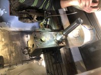
Removing the larger round end-cap (black, threaded and a seal) reveals the large 'bushing' as you've see in Pic below. 4 bolts to loosen. The eccentric of the worm shaft can be moved CW a hole at a time. There is a spanner inner worm-shaft bushing w/ 2 hole set in mine.

We did remove the motor cover set, the motor belt to just let us turn and observe via the fluid glass we removed to gets eyes inside. note- the unit will not turn w/o the platter secured.

Some observations:
Turning the worm shaft by hand led to consistent tension and even turning except for 2 small positions. And only a few worm-teeth wide? (pic 2 w/ the red lines)

This is the present issue to try and solve now. Moving the backlash adjustment 2 holes CW puts the lash at 2-4 tens. But the bind on those 2 marked spots are bound significantly more while inside the lines compared to the rest of the turns

Soooooo for about 1/2" or a few degress of bind out of 360 total... We're going to see what we can learn tomorrow what's going on. The Brass worm was spun around 2 or 3 times while we looked on w/ the Magnifying glass and some light. Wondering about some blue marking?

IMG-4625.jpg IMG-4623.jpg
 
Hey all - So heres the update and probably (hopefully) last post for a bit on this.

Called for support - Talked to the rotary guy about the even Lash mins the (2) different 3/8" travel or so tight spots. they are about 2" apart. for a 97 unit. Not shabby is the feeling.

-Used denatured alcohol to clean and flush.
-Used Blue on brass worm gear in a few spots and ran it through some paces.
-Adjusted Backlash bushing 2 holes CW. Now getting .0002 to .0003 lash (less in tights spots) Originally 8tens to a bit over a thou. I would call it.

The bluing Observations;
-It's a bit hard to see super well but you can see the mesh marks.
If the gear is a vertical and edge on below here is what we saw.


_____________ Top of gear edge on looking thru fluid glass (removed).
------ <----Mesh marks.
------
------
---- <----- tight spot starting (spinning shaft by hand force (or binding starts))
---
--- <----- most force required. tightest spot.
----
------ <----- returns to normal spin force.
------

We're still not convinced it's the worm ... but We chatted and thought "well - if the mesh is tight and it cannot smoothly seat with the worm shaft, lets check the mesh marking. The marks may not even be part of this.. But we took this as far as we could.
Pics: In the pic with blue, (non bind example) -vs- the other (which I can zoom in and see those short darker lines)
IMG-4632.jpg
IMG-4635.jpg

Calling it a wrap! It's back together, with the lash adjusted, connected as a bones only and running as A for some burn in. IT goes past the bind parts w/o incident. Support noted that would be the best option for this thing w/o spending $$$.
Putting it all back together tomorrow and calling it! ONWARDS!

GC
 
... Thought I would add to the story for HRT / TRT folks as there are some further good tips we learned.
This went from backlash adjusted and 1 hour from power up to full on tear down and more parts on order (seals, a bearing and a proximity sensor).

What happened: we ended up with a missing spring. (Personally I think the kid did it on purpose as he was bugging me to do a full tear down anyway.)
IMG-4727.jpg

The lube-wicking system used to pull lubrication from the case to the platter's underside is accomplished via an aluminum tube in the chassis, a small spring inserted into alu. tube, and finally- the long wick inserted over the spring and into the alu tube.

CAUTION: Do not pull out the Alu tube too far if the spring and wick are inside. the spring can slip out from the tube bottom into the main case cavity.
...and that is why it all came back apart.

All in good fun! Some points below and I'm glad he did the tear down actually. it was contaminated and we had a bad needle bearing on the worm shaft anyway on inspection.

Some pointers on the HRT insides if you end up in this place as newbs like we were.

0) This was not hard or overly difficult. Just take a lot of pics and notes.
1) you MUST remove the proximity sensor from the side chassis if you want to do the full tear down. The sensor is about 1mm away from the magnet on the worm gears inner mount point. The brass worm teeth will ruin the proximity sensor if not backed out before you remove the entire assy.
2) The seals.... They are inexpensive and easy to replace. The final platter ring does require you to 'set' it back out of the channel (you'll know when you get there)... We simply wrapped fish line around the o-ring, ensure it stayed in the groove of the platter, and gently put it on the HRT unit. Using the line, pull down and over.. You'll hear an actual 'snap' as it comes out of the channel and pops onto the platter and chamfer of the back side.
3) When you adjust the backlash w/ the worm shaft adjustment - (see other post we did on the actual procedure) The point: We were told you can/may have some stiff spots in places after moving the shaft a hole or two. We did and it was in 2 places. If the motor turns thru it with no stalling or errors take place - Run it. (which we did rather than spend a lot of money on new worm and shaft.
4) The Motor and Encoders.... you can get the encoder off. you can even get to the glass on the encoder to clean if if you so wish.... if you ruin it. you will be getting a sub encoder. I found several vendors with a substitute Renco encoder. we did clean ours... some film after 28 years but it went back together fine.
RENCO OEM (no longer avail) RHS21D-P1-2000-8mm-5-CS-LD-M1 P/N: 78994-008
Replace w/ (We did not need.. Just providing list from Vendors I contacted who noted Renco subs).
(5) Motor brushes- Clean em out.. our's had a lot of carbon dust. Ensure you put each back in the exact same orientation and same brush hole.
(6) the aluminum tube for the wicks. Do not shove them to the bottom as a hard stop... They ride above the chassis bottom say 1/8 or so to let oil flow in. We snapped pics of them OEM-as-is.
(7) find the Haas rotary promo video from their factory floor! Super detailed and shows a full assy. Play it backwards for tear-down. ) :-p kidding but it is a SUPER vid for an HRT wannabe tech.


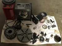
and if your shop looks like this on re-assy day, then I think the kid would be proud. (I had a fit.. but he thought it was just how you get from the part layout to reaasy of each section 2 ft closer to the mill each time = A finished HRT on the table. ... sh*ttt what do I know right. it worked for him :willy_nilly:
IMG-4784.jpg
 

Attachments

  • IMG-4784.jpg
    IMG-4784.jpg
    96.6 KB · Views: 77
Thanks again for the updates more pictures the better. its great reference material for those who may need it sometime.

Thanks


Back
Top