What's new
What's new

Advice on Plan of Attack: Sandord SG-48 Surface Grinder

twalsh341

Aluminum
Joined
Nov 12, 2008
Location
Philadelphia, PA
Hello Everyone,

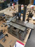
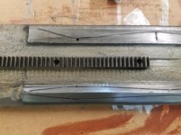
I picked up one of those tiny Sanford grinders recently and I've got it almost completely apart. I've got a small list of parts to make, and new gears to fit. Fortunately a lot of these parts can be had off the shelf and modified to fit.

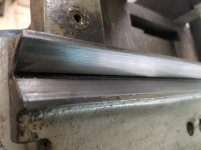
Today I cleaned up the ways with solvent and inspected the travel of the table with an indicator on a mag base on the column. I have a slope towards the rear of the cross travel of -.014" and a slope towards the left hand side of the machine travel of -.003". I inspected the v ways in vee blocks and they have some wear to the 90 degree v, but are straight to about .001", meaning most of the wear has to be on the carriage.

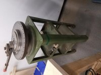
There is wear on the column too, but I haven't inspected yet. The spindle feels smooth, and doesn't have a lot of end play, I haven't inspected that yet either, but I'm hopeful that it'll be in pretty good shape.

I have done a little bit of scraping to get two flat things into mating contact, but the complexity of all these surfaces is a lot to wrap my hear around. I'm reading through "Machine Tool Reconditioning" to try to work out a plan of attack.

I feel capable of scraping the column ways into alignment and square to the base,but the next step after that is to scrape the v ways, which I'm pretty intimidated by. I think I need to make a 90 degree gauge block, with the vee 45 degrees to a flat that I can indicate to ensure that the V is aligned properly. Since these v ways are removable, with locator pins, and measure only .765"x.765"x 8.00" does it make sense to send the vee ways to someone with a tight surface grinder to grind these, then use them to spot and scrape the carriage? Then put my big boy pants on and tackle the vee/flat of the table with the scraper?

Thanks!
 

Attachments

  • 20190521_142719.jpg
    20190521_142719.jpg
    96 KB · Views: 153
It looks like the grinder is sitting on top of a bench. Is it steel or wood? The leveling shim screws holes are not used. You may have to set the grinder on 3 points. How do you expect precision when the machine is like this? In order to advise you the correct way you need to have the machine supported on a steel bench or surface plate. Also show us the machine apart and take a lot of photo's of the worn area's. Surface grinders are a single point design where the wheel hits the table. To indicate the where the wheel would contact the table. Then after you have done all this you will need to scrape the top of the table top to relieve the work hardened iron under the chuck before scraping the table ways. If I were doing it I would buy or rent a camel back straight-edge longer then the ways. I would not make a 90 degree prism as that is a waste of time. You shouldn't remove the ways and send them out. Leave them on the table and machine or grind them as a unit. More photo's please.

I found these, it may help: Sanford Miniature Surface Grinder and
http://vintagemachinery.org/pubs/10678/18132.pdf
 
Last edited:
More Photos

dkmc, it doesn't show signs of a drop or fall, no bent, cracked, braised, or dented locations that I can tell. The cross feed screw is worn to about half the thread width in the middle, and one felt on the table is missing. so I wonder if someone just stopped oiling it or otherwise fiddled with it sometime in the past.

Mr. King, it was on wood to begin with, I've put it on a surface plate, which itself is resting on 3 points on a rolling tool cart, does it need to be leveled for me to do an more accurate check?

That did make a bit of a difference. As far as I can tell, it is a bit more in plane, I also mapped the pad at the position the wheel would be in. The motor was not attached at this point, but I attached it and the spindle then remapped the table. I was worried about it tipping backwards, and off the surface plate so I lightly applied two clamps for insurance to keep it from tipping. Is this a bad move?

I'll attach as many images as I can to show the wear of the ways, and add posts with more photos if necessary.
 

Attachments

  • Sanford #45-798 pad map.jpg
    Sanford #45-798 pad map.jpg
    86.8 KB · Views: 90
  • Sanford 45-798 inspection.jpg
    Sanford 45-798 inspection.jpg
    94.8 KB · Views: 101
  • Pad.jpg
    Pad.jpg
    90.7 KB · Views: 86
  • Long vee.jpg
    Long vee.jpg
    86.4 KB · Views: 100
  • Carrieage vee wearing.jpg
    Carrieage vee wearing.jpg
    92 KB · Views: 101
Post with photos of wear on the ways. One more post to show the double vees that the carriage rides on.
 

Attachments

  • Table flat way scoring.jpg
    Table flat way scoring.jpg
    88.1 KB · Views: 97
  • Table v:flat and rack.jpg
    Table v:flat and rack.jpg
    90.7 KB · Views: 109
  • Spindle housing .jpg
    Spindle housing .jpg
    90.7 KB · Views: 101
  • Carriage vee 3.jpg
    Carriage vee 3.jpg
    94.1 KB · Views: 83
  • Long vee.jpg
    Long vee.jpg
    86.4 KB · Views: 84
This also includes a few photos from indicating the pad.
 

Attachments

  • Double V Wear 2.jpg
    Double V Wear 2.jpg
    84.9 KB · Views: 65
  • Double V wear.jpg
    Double V wear.jpg
    87.3 KB · Views: 66
  • 20190522_131918.jpg
    20190522_131918.jpg
    85.7 KB · Views: 68
  • 20190522_131930.jpg
    20190522_131930.jpg
    84.4 KB · Views: 78
  • Double v wear3.jpg
    Double v wear3.jpg
    87.3 KB · Views: 76
From the looks of it, it looks like someone tried to rebuild it and scratched the ways with a sharp cornered scraper blade. Someone bought a Sanvik or Anderson scraper that comes with flat blades and didn't know they were suppose to re-sharpen the blade with a radius. It looks like the saddle ways is longer then the base ways. So you would scrape it first and make that your master to match fit to the bottom or base ways.

It looks bad, but I wouldn't send the table, saddle or base out to be ground because the time and expense of that would be more then hand scraping it. Once you flip it over and begin to look for original surfaces to measure from you can guess at how and where it is worn. It's worn and you will need to fix it. I have seem machines a lot worse then that, so don't worry about it. As far as the base on the surface plate remove the headstock and while it's sitting on the plate unclamped use a dead blow hammer and tap on the 4 pads and listen for the same sound … A solid thud is good. if one side makes a different noise it is open, Ideally you could scrape the pads so the thud is the same noise or if those holes are tapped or could be tapped you could make leveling screws and adjust them as they rest on a flat steel plate with a counter-sinked hole where the leveling screw would rest. You could lay some thick paper on the plate or thin leather under the flat 1/4 x3 x3 plate so it ould not damage the granite.


You will need to buy or borrow a camelback straight-edge to scrape the long side saddle ways after you have set it on 3 points on a solid table or steel horses. Once you have it flipped over take some photo's. I don't have time right now to go into it more, but you will need to scrape the shorter base ways too to prepare the short ways before you blue up the longer saddle ways to match fit to the shorter base.


We or you will scrape the sides of the parts that are not worn as bad so the chuck surface will indicate better as you scrape and test. After your done you will grind the table top and it will offset the bad numbers you are reading, so they need not be worried about to much now. Another thing to think about is those short ways are high in the middle and the long ways are probably high on the ends. I have a couple of former students in Allentown area who I believe have some straight-edges. One is Mud ( I sent Mud a note) a member on here. He has scraped and rebuilt a couple of machines and he would be a great source. Also Drew Devitt (Cody too) of Moglice owns a King-Way and some straight-edges and they may give you a hand.
 
Thank you Mr. King for taking the time to point me in the right direction and make some connections to people that might be willing to help.

So would order of operations be 1. Scrape the base (feet) flat to the surface plate, 2. Scrape table pad for chuck flat to release stress, 3. Scrape long v/flat slides of the table to use as master on carriage, 4. Scrape double v slides on carriage to use as master on base, 5. Scrape base v's, 6. Scrape, column assembly/spindle, 7, scrape bottom of chuck, 8. Grind pad, 9. Mount chuck and skim cut.

Should all of this happen before painting but after rust/paint removal? Any problems with using 30psi fine glass bead with a thorough cleaning and masking of oil ports and way surfaces? I know for the replacement cross feed nut, it's position will change after being scraped in lowering the table in relation to the cross feed nut, and the rack/gear assembly.

The longest part to scrape is the column at 15" the longest table way is 12.5" I will probably go the route of buying an 18" casting to machine and finish it for scraping practice.

I have three table options, photos shown below. A 2.5" thick wood and tube steel table that the Sanford came on, a wood shop table and a heavy steel stand, currently has a bender on it, but I could take that off and tap for three leveling points for the surface plate, or grinder base and steel plate as you suggested or as the scraping station for the table. Does one of those options fit the bill or do I need to look into a better table?

The last two photos are of the SG table on the surface plate, the pad does stick to the SP (Does that mean anything at this stage?) There are original frosted surfaces on the back edge of the flat, and crest/valley of the v way. The table ways are 12.5" overhang the length of the pad by 2" on one end and 3" on the other. I indicated the flat with a .001" test indicator (the finest I have at the moment) and discounting the flaking grooves it's under .001" the whole length on the unworn area, the wear is deepest right next to the unworn strip around .0015 to .0025" and worn about .001" on the inside edge of the flat. The V shows a hollow in the center section of the prism, which you can just see crescent sliver of light under the 6" rule in the next photo.

dkmc, what all do you have to do with your machine, do you need measurements of any parts?
 

Attachments

  • 20190523_144105.jpg
    20190523_144105.jpg
    91.8 KB · Views: 65
  • 20190523_144114.jpg
    20190523_144114.jpg
    96.9 KB · Views: 54
  • 20190523_144130.jpg
    20190523_144130.jpg
    98.8 KB · Views: 60
  • 20190523_161648.jpg
    20190523_161648.jpg
    84.7 KB · Views: 62
  • 20190523_161716.jpg
    20190523_161716.jpg
    92.3 KB · Views: 60
Forgot the photos with the scallop in the v way.
View attachment 257142

The bottom looks like it is original and the top is worn (the way the picture is now) so ou would depth mike the worn compared to the never worn area at botom. Then you would first scrape (on that part) off the original non worn area and tip in the worn area and save the geometry of that V way.

Many nver do that and the scrape the worn and unworn area after bluing it up and change the angle steeper then it originally was. Causing 3 times more work. You need to make a plan and get advice from us (the experienced rebuilders on the forum) before jumping in with your own idea and making more work and then dissing rebuilding. I have other things to do and can't write everytime you do. So relax. Plus its a holiday weekend.

You have to start at The bottom and work up, but scrape the long side of the way system first and then prep the short side before "Match" fitting the long side to the short side. After the saddle bottom is done you would scrape thelong side of the table way system. The majority of the time the table as it is the long way side and match it to the top the top of the shorter side ontop of the saddle after prepping the saddle to "Match" fit the table to the top of saddle. Both saddle bottom and table would need to be set on "3 points" for 24 hours so they can self level normalize stress in them before using a camelback to scrape them. Camel back needs to be longer then the way your bluing up. The column would be scraped 2 nd to last and headstock last. then grind table top so it is co-planer to saddle and table ways. cu later. Rich

Picture examples are lathe, mill and grinder. showing long st edge vs.short ways, tapping on table to be sure it fits ways under it, (Myford grinder I rebuilt) yellowing up unworn area to scrape first to not change the geometry of way when scraping, and 3 points used on Bridgeport table.

Another thing. I make and sell straight-edges, teach rebuilding plus rebuild machines. It has been my primary way of income for my whole life. Not a hobby.

20180929_101830.jpg2014-02-26_13-50-05_372.jpg2014-02-24_11-34-35_214.jpg20160318_074312.jpg20160318_074212.jpg


Back
Top