What's new
What's new

Cracked lathe bearing

tribe

Plastic
Joined
Jul 6, 2014
Location
Vienna, VA
Hi folks

I'm not sure if this goes here but I hope so

I just discovered that the bearing on my pretty new to me SB 9 is busted... It's a real pitty because it will take a while until I can find a headstock with low wear like this one (but no crack)

I know the whole headstock is shot but I would like to try to fix it. My question to you is which way of soldering/brazing/ welding would you recommend for this?

The reason I want to try to fix it until I find a new part is that the broken part is less than 50% of the circumference and the spindle still sits in there pretty firm...
 

Attachments

  • ImageUploadedByTapatalkHD1406413931.335029.jpg
    ImageUploadedByTapatalkHD1406413931.335029.jpg
    17.9 KB · Views: 558
Tribe, your post does belong here and I thank you for posting it. I do try to keep general repair questions away from this subforum but yours is not a general repair.

Some will probably offer different opinions but from my experience with brazing and soldering I wouldnt try it with your parts. The best solution for you as the part will fit nicely where it came from is to strap it. That is to make a nice steel strap, at least 1/2" thick that will fit over your broken part and bolt that strap down. It will act as a clamp and you should get many years of service out of your bearings. If you are careful and creative you can even make the strap look like some turn of the century part and call it a special feature. :)

If you are having a hard time visualizing the idea think of an engine main bearing cap placed over your bearing helping to hold the broken off piece in place.

For all the load that lathe will need to handle the strap should be enough. Now your photo is a bit small for me so if I have missed something important I am sure you will understand.

Charles
 
I would suggest strapping it, if possible or using as-is if it'll run with care. Then manufacturing a new bearing shell out of DuraBar or similar. One of the glorious things about a lathe is that it can, darned near, make itself.
 
Ok got it. I had thought about a reinforcement (strap) but I didn't think it would be the better idea. I will file a flat on the top of the bearing and make a piece on the mill. And will try to make it look like a feature! ;)

I don't understand when this thing broke...and it doesn't look like a new crack? If it wasn't for some oil coming out of the crack I wouldn't have noticed it...To test it I made some deep'ish cuts with the lathe and the crack doesn't move at all.

Thank you Charles for your prompt and cordial response! This forum is great
 
Strapping to pull broken iron castings together is a fix as old as the hills. It is well proven, and was used on everything and anything- freeze broken engine water jackets and water pumps being a common thing repaired with strapping. The beauty of a fracture with a clean break is that it has a "unique" joint. The irregularities in the fracture will mate up perfectly, in exact alignment, and will "key" the broken parts together so they do not move relative to each other. In fact, "fracture joints" were used in making steam engine flywheels, Jacobs drill chucks, and automotive connecting rod big-ends. Make up the capscrews which hold the bearing cap in place so the cap is rigidly held. Then, you can file the outer surface of the cap to dress it into a portion of a cylinder. Once you have done that, you are ready to fit the strap. My own method uses what I've learned from seeing this kind of repair, and my own experience. First, I make a shim out of soft copper. A piece of copper roofing flashing is fine, and anneal it so it is dead soft. Wrap the shim around the bearing cap. Next, cut a piece of steel flat bar for the actual strap. I'd use steel about 1/4" thick, and use something like A-36 (structural steel, hot rolled). My method of forming curved saddles and similar is to do them cold. You can weld 2 pieces of 1" diameter round bar to a piece of plate, the round bars being set parallel to each other with a gap of maybe 1 1/2" between them, or you can use a blacksmith's swage or swage block, or you can use damned near anything that has two solid edges with a gap between. The round bars produce less dinging or cutting into the outer circumference of the strap. Lay the piece of flat bar so it spans the gap in your swage, swage block, or home-made swage. Take a ball pein or cross pein hammer and start lightly hammering the portion of the flat bar that is bridging over the gap in the swage or your home made tool. As you start hammering, the flat bar will start to curve. You move the flat bar and keep hammering. More hammering tightens the radius of the curve. Use the bearing cap as your template to try the strap on.

Ultimately, you want the strap to be a good fit on the bearing cap, with the copper shim sandwiched in. Some filing on the inner circumference of the strap and dressing of the ends is to be expected. With very simple means and patience and a good eye, you will be surprised at how nicely this method works. Done it LOADS of times to make saddle plates, wrappers, and straps. If you get into hot-working the steel strap, the tendency is for the steel to "draw out" and wind up longer and thinner than what you started with. If you have an oxyacetylene torch with a small brazing tip, you can try some localized heating of areas to a red or orange-red heat if you need to tweak or bend them to make the fit happen.
By in large, cold forming should work for making the strap, with hot forming only needed at the end for the final fitting.

Once you are satisfied the strap is a good fit on the bearing shell, marry them together with some socket-head cap screws. I am guessing that 10-32 would be about all the big you want to go. I'd start with capscrews tying the strap to the bearing cap located at approximately 11:00 & 1:00. This leaves the 12:00 area free from tappings as it is the point of maximum stress in the bearing cap. Drill the strap with the tap drill size you are going to use, and use the strap as your drill jig. You might want to put a collar on the twist drill to make sure you do not overdrill into the bearing lands or worse. Drill the tap-drill sized holes in place using a hand-held drill. When you get the hole at 11:00 drilled to depth, open the hole thru the strap to the body drill size, and then counterbore for the socket head screw. Tap the hole in the cap and run in a socket head capscrew. Go to the opposite hole at 1:00 and do the same thing. Snug the cap screws. Work your way around the strap from the center to the flanges at the joint on the bearing cap. The capscrews get drawn up in a sequence, and you do not tighten them any more than needed. The soft copper will deform or "flow" to take up irregularities between the steel strap and the bearing cap casting. Makes for much better contact and avoids the strap and bearing cap only making contact at a few random points.

This is the old timer's method of fixing a broken casting where precision enters the equation. Any sort of welding or brazing processes would put heat into the casting and the post weld stress would distort the bearing cap. We are talking of parts that are line bored and finished to better than tenths of thousandths of an inch, so welding or brazing - while joining the broken casting pieces- would pull things way off. Very fine work is needed, and while you want to stabilize and join the broken parts, you need to do it in a manner which maintains the alignment of the broken pieces relative to each other, and does not add any stresses that force things out of line. The strapping has to be done carefully, and the last thing you want to do is try to force the strap to fit the bearing cap by using the cap as a forming block or similar. I've formed a lot of curved pieces using just the gap between the jaws of my heavy machinist vise of blacksmith leg vise, or with swages or home-made forming tools. The trick here is not to try to force the metal to bend around a duplicate "positive" or "male" form in the shape of the bearing cap. Using a simple swage and light hammer blows, you can move the metal a lot easier and smoother and make a nice curve with great control.

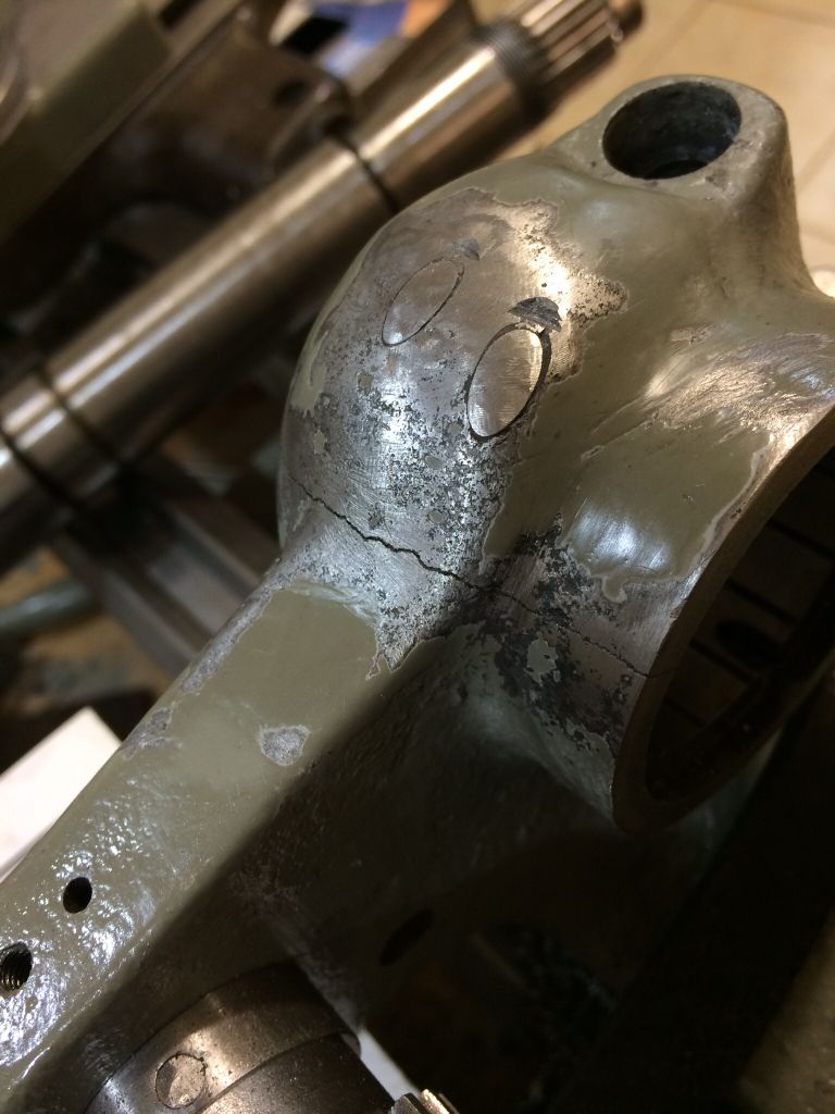
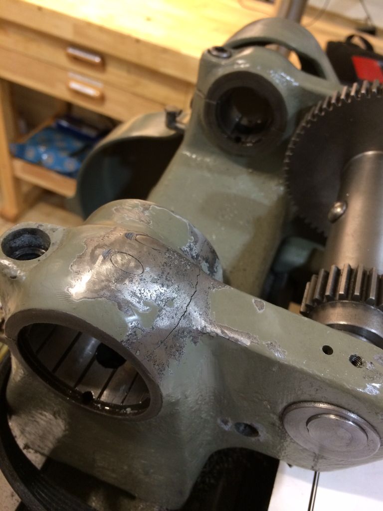
BTW: I erected a steam engine years ago which had a flywheel that was in two halves. The flywheel weight was 8 1/2 tons. The wheel was cast as a single piece, with cores in the rim of the wheel at about 3:00 & 9:00, along with flanges with cored bolt holes. The hub had similar cores, and bolting flanges. The rough casting of the wheel had been machined as a one piece casting, bored for the crankshaft and the keyway cut. It was then put on an arbor and outer diameter and rim faces machined. When that was done with, Skinner engine's shop used to "pop" the flywheels into two pieces by driving steel wedges. The fracture joint was unique to that wheel. The engine I re-erected was built in 1926, and I re-erected it overseas in 1981. We got the flywheel bottom half in the wheel pit in the foundation and then brought in the crankshaft, which also had the generator rotor on it. We set the bottom half of the flywheel on wood blocking so it was a little low, and put a hydraulic ram ("Porta Power") in the wheel pit to jack up the lower half of the rim when the time came. We cleaned the fracture joint on each half. We rigged in the top half and had it hanging on chainfalls. The halves were joined by about 1 3/4" diameter steel studbolts with fine pitch threads. These studs got heated to a "black heat" in a fire before installation. I put a little kerosene, a few drops, in the center of each fracture joint on the bottom half. We then let down the top half, still on the chainfalls, so it just rested on the crankshaft. We came up on the Porta Power so the bottom half just met the top half. We started putting in the studs in a mad rush as they had to go in hot. We ran the nuts down and slugged them up. When the studs cooled they drew the halves together in a real death grip. The proof as to the fit and tightness of the joint was seeing the kerosene and tiny air bubbles around the edge of fracture- the joint line was closed tight and just a wavy or jagged line. This was a fracture joint that utilized the inherent locking ability of a clean fracture. Your bearing cap is doing that same thing. Be extremely careful in how you handle and fit those pieces together as you need to keep the fracture surfaces "crisp and sharp" for the fracture joint to do its best work at locking the two pieces together. You mention seeing oil coming out of the crack in that bearing cap. That oil is your clue that the pieces are moving very slightly relative to each other. Machinery gives very subtle clues, and you keep your eyes, ears, and senses working and wits about you and you can read them. The cap sits on shims, and the shims can act as a sort of leaf spring, just a little resilience or "softness" in them. It's a catch 22 whether you tighten the cap up to come down hard on the shims, and risk opening the fracture joint. Some person in the lathe's past may well have gotten too frisky and sloppy in reassembling the cap onto that end of the headstock and pulled the capscrews unevenly, or messed up in the shimming so the cap was un-evenly shimmed and then tried to sock up on the capscrews to get things closed.

I've had a Southbend Heavy 10" lathe in my shop for almost 30 years. It has the bronze bearings. It was old and tired when I got it. I freshened up the bearings, and have done more work on that lathe than I can recall. Big jobs like wheel spaces for our tractor, and fine small parts and everything in between. The lathe is never entirely clean. Seems like when I clean it up and wipe it all down, I wind up machining cast iron or something to make a real mess of chips in a big hurry, and then another couple of jobs crowd in. For all the visible wear on that old lathe, it holds pretty tight accuracy and surprises me all these years later with what it can do- stuff like chasing a 6-32 or 4-40 thread, or making heavier parts seem all in its reach. Never underestimate an old Southbend lathe. Never underestimate your own mind and imagination at what you can do with that lathe, and how you can repair it. As I've come along in my life and career, I've learned that about 99.999% of the time "there is no single right way to do anything". If the end result is what is needed or meets the drawings and specifications, who cares how you got there ? As a kid learning to write, I had fine motor skill delays. I held my pencil my way and printed nicely enough. The teachers would grab my hand, "correct" me, and holler. As soon as they were off and away harassing some other hapless classmate, I'd write using my method. At home, I ate my meals holding my knife in my left hand, fork in the right and never put them down or changed hands. I was polite, asking to "please pass the peas" and saying "excuse me" if I needed to get up from the table or say something, so it was not like I was all hands and fingers in the food stuffing it into my craw. But, Mom would keep telling me the "correct" way to use a knife and fork. Hell, I was using TOOLS in Dad's shop and had tools of my own and was not getting maimed too badly. Dad was showing me tricks to move stuff with pinch bars, rope falls, or how to run pipe or nail up framing and each situation seemed just a little different. At the dinner table, I was not breaching any etiquette at the table that I could figure and I was not leaving anything on my plate, so what was the big deal ? At age 6, I realized: "There is no single right way...." In machine work, this is much the case. If you ask some "experts" they will tell you to go hunt up another used headstock, then you are into scraping it to fit your lathe's bed, then you are into checking the alignment of the tailstock to the headstock.... Another "expert" will tell you to part out the lathe and junk the headstock..... Here, most of us will tell you it is fixable, and probably a few different ideas about doing it.

Joe Michaels
 
Epoxy thins with acetone or denatured alcohol.

Strapping will be full support.

After all is fitted and ready for assembly you can clean the mating surfaces then mix a batch of very strong epoxy and thin it down to paint consistancy.

A few drops of oil on the spindle then paint the faces and touch together to make sure full coverage and wipe off excess on inside.

More oil on spindle and assemble cap on spindle with strap.

Oil is to block epoxy from spindle.

After it cures for a few days you can remove cap to verify no epoxy on spindle and you should be good.
 
You could bolt it together
Drill 2 holes in the broken of piece at 90 dgr of the crack The same size as the cap screws you wanna use
Bore or dril pot holes on the opposit side
Then clamp it all together in the right position Drill and tap holes in the base and bolt it all together
I have fixed cracks on numerous occasions like this and it works great and it looks like original if you sink the potholes deep enough and put some filler on

Peter from holland
 
To Joe Michaels: Thank you for your essay. I enjoyed it to the last word. It's a mixture of wisdom and history, and very valuable information. Regarding the steam engine you talk about; I lived in the south of Argentina for 20 years and have been to some 100 year old lumber mills with a central steam engine driving a world of underground pulleys and belts... Everything was either leaking oil, or water, or tied with wire, but it was working, and it worked every day. With no spare parts. I learned there that everything is fixable. I've also seen the steam engines driving generators!

I have to admit that I first posted my problem here thinking that the advise would be to change the part or throw the lathe away, and a bunch of safety warnings... And boy was I wrong. I love you guys

Thanks ALL for the valuable tips

Pablo
 
Pablo, thank you for the kind reply. The steam engine I referred to in my post was in Paraguay, about 100 miles from any paved road. The South American sawmills you describe are true to form. Many were driven with "Locomobile" type steam engines, and some were a mess of old boilers, tired engines, shims cut from old tin cans, and piping scabbed together with bubblegum or birdshit welding. But, they cut a lot of wood.

I developed a very deep admiration for the South American people when I lived and worked amongst them, and perhaps something of a bonding and understanding of the culture. A junk pile in the USA is a supply house to South American mechanics (and to me). I also learned there is an unspoken bond between peoples of different cultures despite a language barrier, if those people share a common craft. Seemed like if I saw some South American machinist or mechanic in a "Taller" with a sign that said "Torno" (lathe) and looked their way, they'd make me for a "Gringo", but also make me for someone who was a kindred spirit- a machinist or engineer. I'd be invited in and made welcome even if I had no business there, and we'd hang out for a few minutes. Travelling the roads in Paraguay was a life changing experience for an American. Two rut clay roads, and it was wise to stop for the night and not push on. We'd see a fire in a field or clearing and stop there. Truckers would have pulled off for the night and built a fire. We'd join them around the fire and we'd share food, whisky, beer, and I'd get by with some fractured Spanish I'd learned on the jobs. Some trucker might have a guitar (no cell phones, no CD's nor boom boxes back then), and I'd pull out my old harmonica. We'd play music for awhile, and everyone in the most remote corners of this world seems to have watched American westerns. I'd play "Red River Valley", bending the notes, and the guys would look at the fire and hum along, and I'd play "Home on the Range", with about the same result. Soon, we'd turn in, sleeping on the ground. No one thought about robbery or worse, even though we were in the middle of nowhere and I was the Gringo amongst a pack of South American truckers. It was much the same with the crews I worked with. Bonding was quick, and they hung on me to learn what they could- and I did my best to teach everyone all I could. I did not eat until I was sure my crews were fed (or made sure they had food and clothing), never put anyone on a job I could not do myself, never asked people to get up on the steel or do anything I wouldn't do. Simple rules for myself that I never thought of as rules, just treating people as I'd treat myself. Never had anyone hurt on many jobs in SOuth America as a result, and always had a hard time leaving the crews I'd worked with. To this day, not a piece of scrap steel, shred of gasketing or shim stock gets by me. I have this weird ability to mentally file all the scrap, where it came from, where I ratholed it, and many years later, those little bits of scrap get used handily on projects. Call it the South American influence.

The smell of meat cooking on a hardwood fire will usually take me back to South America as that was the common means of cooking, either on hardwood or on locally made lump charcoal ("Carbon"). Whenever I hear the song "Pasa del Condor" (? on my Spanish- "Flight of the Condor"), I am taken back to the jobs. Simon and Garfunkel pirated the melody of "Flight of the COndor" for their own song "I'd rather be a rock". It's an Andean melodyand most usually played on reed pipes. When we'd hit some milestone or other on some of the jobs, the men would bring in local musicians and we'd have a little party, roasting a pig and plenty of beer. In Ecaudor, the bands played the reed pipes (Rondador, I think they are called). When a real local band played Pasa del Condor, they had these giant reed pipes, kind of like freight train whistles. They'd start that song like a steam locomotive breaking a freight train loose. The song seeped into me, and its convoluted melody always causes me to envision my old crews and the infinite patience and ability to "make something out of nothing" those guys had, working slowly, working very hard, never complaining, just finding ways and making things happen that a US crew would have run the other way from. My time working in South America gave me a very different perspective. It occurred fairly early in my career, and was a life changing thing for me. I am glad I had the experience, and have applied it over my career and into the rest of my life. I welded a grill together out of steel plate and half an oil drum for the cover or "clamshell", and many of our meals are cooked on hardwood. Never owned a gas grill, never will. I grab a glass bottle of beer and sit by my grill when the meat is on and the smoke is swirling out the bung hole. With thunderstorms and heat, I moved the grill near the garage door. I'll sit in an old desk chair in the garage looking out at the grill with my beer. Wife will come out and sit with me. The LeBlond lathe is still on skids in the garage- doing jobs while lagged to skids, and the old camelback drill and blacksmith vise, anvil, and oxyacetylene and welding gear are there. Wife sits in a canvas chair and will look at me and say: "Reminds you of the jobs in South America, Joe ?" She knows where I've gone in my mind. It was hard work, a lot of trials and a lot of learning and growing, and I think of a lot of it out there in the garage as the wood smoke and smell of roasting meats mix with the smell of machinery. Wife will ask me if I am "playing 'Pasa Del Condor' in my head" and I will smile and kiss her.

If you ever get to NY State, which I hope you will, I'd like to show you Hanford Mills. It's best to google "Hanford Mills". It is an old wooden sawmill and woodworking mill complex, dating to the 1850's and working into the 1960's. It has a waterwheel, and it has a working steam plant and miles of belts and shafting. I do a lot of their engineering, which included designing the re-creation of the 1890 steam plant, and I teach a course there called "Steam Power 101". It includes firing the boiler and running the steam engine when the mill is sawing. It is hands-on, and participants get right into the workings of the steam plant. If you get up this way, "Mi Casa es su Casa, mi Hermano."
 
why did those bolts have to go in there hot? just thinking about motor head bolts for comparison.
 
Tribe;

Look up metal stitching on the internet..
They repair broken castings with swaged pieces of metal maintaining alignment and concentricity..
Repairs have good strength..
 
dian:

Motor (I assume you mean automotive engine) head bolts are small fasteners. The torque applied to the heads of the bolts tightens the threads and puts a "stretch" into the shank of the bolt. It is the "stretch" (actual engineering term is "strain") in the bolt shanks that does the work of clamping the head to the block with the head gasket as the "meat" in the sandwich. On larger work such as heavy diesel engines, steam turbines, hydroelectric turbines, and steam engines, the fasteners are quite a bit larger than what you'd find on an automotive or light truck engine. The making up of joints or connections using the "clamping force" created by the strain in the studbolts becomes a much more closely controlled thing than simple torquing of bolts. Applying torque to a bolt is just that. Torque is a force x a distance from the center of the fastener. How much of the torque is lost to friction in the threads or between the head of the bolt and the cylinder head, and how much of the torque actually is applied to stretching the bolt varies bolt-to-bolt. Torquing of bolts is a very approximate thing. It gets what I'd call "ballpark consistency" from one bolt to the next on a flange or head. What the next level in this process is relies on determining the ACTUAL stretch of the bolts. How to do that ? Every threaded fastener is its own micrometer. Steels are quite predictable materials and nearly all have a modulus of elasticity of 30,000,000 psi.

Strain is equal to "stretch" (net change in length) divided by stressed length (I usually consider this as the unthreaded length of the shank on a studbolt). Strain is expressed in inches per inch, and is usually a very small number.

If you know the diameter of the shank, you calculate the area. Take the clamping force you need and divide it by the number of bolts in the joint or flange, and take that number and divide it by the area of the shank. You now have the required tensile stress, in psi.

Modulus of Elasticity = stress divided by strain

you know modulus of elasticity and you know the required stress you must develop in the stud, so you calculate strain.

Knowing the required "unit strain", you then work backwards using the unstretched shank length, and you get the required "stretch". This will be a value in thousandths of an inch.

Now, your trail diverges and you have a few possible paths to get the required "stretch" into your studs.

-you can do it by brute force, i.e.- using wrenches and either cheater pipes or slugging wrenches and sledge hammers
-you can do it by applied force and save your body- using modern hydraulic wrenches (Hytorc, Torcup being the major players in the USA)
-you can do it by heating the stud to get some expansion on it. By calculating the thermal growth of the stud as a function of temperature, you can determine how hot you need the stud to get the stretch. Not quite so exacting as the stud will be cooling as soon as you pull it from the fire. Steam turbine casing studs are gun-drilled thru, and electric or gas fired heaters are used to heat the entire stud thru these drillings.

Now you get into the issues of how you measure the stretch for the brute force and the applied force methods. The answer is by either direct measurement (use of depth mikes, dial indicators, or similar), or by "turn of the nut". Remember I had said: every screw thread is its own micrometer. Say you have a stud that has 14 threads to the inch, and you need 0.020" stretch. You run the nut down snug and take a little more on it to pull out any backlash or slop in the threads.
At that point, you are "zeroed". 14 TPI has a pitch = 0.071", or the thread will advance 0.071" for each full turn. Divide 0.020" by 0.071", and you find this to be 0.283 turns. Multiply 0.283 x 360 degrees per full turn, and you get 101. 88 degrees. Now, one flat of a hex nut gets you 60 degrees, so you can take the circumference of the circumscribed circle (the circle that goes "around the points" of the nut), and do the math to get the remaining 41 degrees of movement, or you can quit the hair splitting at this point and just say "turn 1 flat plus 2/3 of a flat" and call it done.

All this is well and good if you can get to the nuts and things are of a manageable size and you have the tools for the job. If not, the method of heating the stud bolt shanks works quite well, but not with the degree of control you'd find in the other methods. On a 1.750" stud with fine threads, who wants to stand on a plank over the flywheel pit, stooped and twisted, with a 16 lb beater hitting a slug wrench to draw up the nuts ? Skinner Engine said to heat the studs to a black heat, (steel in the studs not heated to the point it becomes plastic) and run the studs in. Slug up the nuts to be sure all the backlash and slop are out of them, and that was work enough in the location the studs were in.

The considerations in any of this are to make sure the stretch of the stud does not take the developed tensile stress in the stud's shank beyond the yield point stress. I design this sort of thing with an allowable developed tensile stress not to exceed 0.5 Fyield. My own rule of thumb. Engine, turbine, and similar heavy machinery designers will specify the "strain" on various fasteners when making them up. O & M manuals will have this information. If not, it is a good idea to "play with some numbers". Suppose you had a locomotive boiler steam dome cover with a copper ring gasket and maybe 16 studbolts to pull the cover down. How tight do you go ? That is determined by the unsqueezed thickness of the ring gasket and how much deformation you think it needs to seat in and seal. You might look at the surface finish on the dome cover and dome top seating surfaces to get an idea how deep a bite into the copper you need to have to get a good sealing. Once you have that approximation, you look at the dome studs and get the threads per inch, and start playing with numbers to get turn of the nuts required. You take the maximum allowable working pressure in the boiler and multiply it by the area of the dome cover, then divide it by the number of studs. This gives you the "pressure load" on each stud, and you realize you have to take it into account when you figure how much "stretch" to put into the studs. You take the modulus of elasticity of copper and use it to calculate the developed clamping force, and do a back check on the stud bolt shanks. Now you are being needled in your own mind by the idea you might just wind up pulling the other ends of the studs out of the dome top flange, so you get into calculating shear stress in the threads. Having satisfied yourself that making up the nuts to squish the copper gasket will not pull the studs out, and knowing the copper gasket is squished sufficiently to seal, can sleep at night. Having done all of that, you come away from your scratch paper and holler at the guys doing the work: "slug 'em up 1 1/2 flats, take it up in stages, and slug 'em in a criss-cross pattern". That being said, you get another mug of coffee and find some other matter to ruminate upon. Come night time, your wife seems to be having a bad dream and wakes you for reassurance. You talk her thru it, give her a back rub, and she tells you she's glad she married a man who works with his hands, not some soft-handed bean counter or desk jockey, and she is back to sawing wood. Now you can;t sleep. So, you start designing and running the numbers on all sorts of things until you lose track of the numbers and start thinking of tugboats and locomotives and past jobs and you drift off. I personally carry quite a few coefficients around in my brain, being from that generation that predated pocket calculators and computers. I know the coefficient of thermal expansion for steel = 0.0000056 in/in-degree F, so have a lot of fun with that, figuring shrink fits and developed hoop stresses in hubs or parts being shrunk onto other parts, or how long a bridge grows on a sizzling day. Mental exercise is the best thing. Keeps your brain supple and healthy. Ipads, Iphones, and similar are going to produce a pandemic of atrophied minds. Learn to think about things like why a fastener is heated to stretch it, think about things like clamping force developed, and just keep stretching your mind. Your mind can be your best friend and can keep you amused, amazed, entertained, and gainfully employed and enjoying lifelong relationships. This kind of work is a great way to stretch and limber your mind.
 
joe, are you saying the studs are drilled through just to be able to heat them up? wow.
 
dian:

Turbine casing studs on steam turbines are usually gun drilled thru. No other way to get the stud heated to expand it/lengthen it when it's time to take things apart.

Joe Michaels
 
Ok folks, I finally had time to give it a try to fix my bearing and I must say that I succeeded.

I decided to try the simplest way first which in my opinion was to drill a couple of holes. I threaded the headstock part and I screwed in two 8mm hardened bolts all covered in JB weld. Once installed I realized that since the 2 bolts are not parallel - they open towards the headstock - there is no way that the part would come loose! So I decided to grind the heads of the bolts off.

When I installed the spindle it was very tight so I had to hit the assembly with a rubber hammer a few times until everything fell in place.

Thank you for all the support and great ideas!

19e08b86636068a2b7427cae97a42079_zpsd9d1ef44.jpg


Back
Top