What's new
What's new

Flaking Patterns

jasaw

Aluminum
Joined
May 26, 2006
Location
Bismarck, ND
I have a question or questions to be more exact. I attended a scraping class last year put on by Richard. In the class he taught us how to half moon flake by hand and also with a power flaker, also we discussed the reason and benefits of doing this. Since then I have seen some different styles of flaking patterns. My questions are, Is there a reason or application for the different style? Also how many different styles or out there? (half moon, cris cross, square cut, butterfly, etc.) Also how do you do/technique some of these different types and styles? What tools and tool geometry are being used?
 
Choice of flaking styles, pitch, density, and depth are chosen mostly by aesthetics leavened by tradition and justified by mumbo jumbo.

While flaking works to enhance longevity there is little solid science to explain it nor have experiments ever been conducted under controlled conditions and the data complied useful engineering tools that can be used to target specific flaking styles, densities, depth, distribution etc to specific application.

In other words, it depends on .the say-so of the most plausible old fart in your acquaintanceship.

Richard King and I have our spats but we pretty much agree on the topic of flaking.

That said, I was never a student of fancy flaking technique. The very few times I had to duplicate original factory technique, I noodled around on scrap until I found a scraper grind and technique that had a close resemblance and went with that. I recall an ancient Wyler block level and some decorative scraping on non-faying parts of a Swiss made horological drill (beautiful apparatus by the way; as handsome a piece as fine craftsmanship and Art Deco design as could be imagined). And that's about it for me. Maybe some practitioners of the black art of decorative flaking will contribute.
 
And just to muddy the waters.

Some sources use flaking and frosting interchangeably to refer to various patterns of treatment after a part is scraped for alignment and bearing. It seems to me to be more sensible terminology to call flaking the addition of regular oil pockets, whatever pattern is used, and to call frosting just a decorative treatment for aesthetic purposes. There could be some overlap since the half-moon flaked pockets are considered an aesthetic treatment in addition to being functional. And, on (cheap) machines with milled way surfaces one often sees a half-moon treatment that could only be considered window dressing or decorative.

The butterfly patterns sometimes seen aren't removing significant metal so couldn't be considered oil-pocketing but would be simply decorative and therefor might be called frosting to distinguish it from functional flaking.

If this argument sounds flaky say so. Disputes or ridicule might frost my ass but it's happened before.
 
I was waiting to write something hoping another student would get involved, Thanks TG. Jason you need to learn to Google these questions before asking them. An old member who doesn't come on anymore, Robert (Lazlo) George told me to use Google to look up old threads. So if you were to Google "1/2 moon flaking, practical machinist" you would get tons of info from old threads detailing flaking.

As all know 1/2 moon is the most popular style, because it's easier to put on and looks good. There is a term "Chicago Job" in the used machinery industry because years ago there was a company in Chicago who would "cut and flake" over bad ways and paint the machine and call it "rebuilt" I saw this a few times down here in Minneapolis, I recall a customer hired me to inspect a machine that had been rebuilt at a local used machinery dealer. While examining the machine I first looked at the way covers and the round headed cap screws holding them on. The hex holes were full of dirt and painted over, a sure sign the machine was not taken apart and rebult.

The ways were shinny and 1/2 mooned. As I walked around their "rebuild area" On the floor was a box and inside it I saw a belt sander and a BIAX flaker. Some rebuild, HA!

I've written and talked about flaking styles in the past. Years ago we all could recognize our work, Or up here I could always tell just by looking at the 1/2 moon flaking that my Dad flaked. His were C shaped and always they had a steady consistent pattern. Now with the BIAX the perfect flake is common they all look the same.

The only time we didn't 1/2 moon was when we rebuilt a G&L Boring machine or Hardinge lathe as they had their own final scrape on the ways, or their "signature". In a recent post I mentioned how I bumped into a Sip (Societe Genevoise Jig bore) Tech at John Deere Tractor Works in Waterloo IA several years ago who had a BIAX scraper and a pull scraper in his tool kit. He told me he power scraped the machine and the last couple of passes he pull scraped his "signature" into the ways.

In the Connelly book chapter 20 goes into the different techniques. Back in the old days several people did there own technique but now we don't have the time to do anything other then the 1/2 moon.

Yesterday I was just talking to my old foreman Craig Laurich who is still rebuilding for a living and we were talking about the Connelly book. In his youth, He used it as a text book as he graduated from Staples Tech School here in MN as they had a rebuilding class 30 or so years ago (not now). Craig said now that he has been rebuilding all these years he scuffs at the book. He said in the front of the book it says something like, You will become a drunk if you scrape" I need to find that...lol

The bottom line is 75% of all machine builders, Machine rebuilders and my students 1/2 moon flake and many use it for Lubrication & cosmetics because they flake the exposed side and I flake the unexposed side for lubrication and now and then at the customers request I 1/2 moon the exposed side. Rich
 
Flaking patterns and techniques

I suppose I'll post my plug here for what it's worth, although Forrest and Rich nailed it.
Working around old school machines everyday I've come across some odd flaking patterns myself. A G&L bore mill rebuilt in 83' by "CHAMP" which has a beautiful resemblance to the perfectly timed overlapping pattern of fish scales. Each mark carries a very mild curve, almost nonexistent curve but just enough to not be a straight grid pattern, but the tangent point so perfectly timed with the alternating rows it looks machine made, though clearly not. A Van Norman no. 36 mill which bore what looked like perfect hourglass shapes in a checker board, not butterfly frosting but .002-.003 deep hourglass flake marks arranged dead square and also longitudinal to the axis of travel instead of 45°, I wish I took a picture. An unknown make of knee type surface grinder which simply has continuous rows of squiggles, like the letter S tied end for end across the column in two directions.
So much if not all of scraping is muscle memory. As each scraper hand comes into his own playing around on a piece of scrap in the beginning, he's bound to stumble upon a pattern or trick that even he's not sure how he did. Turn off the thinker and let your hands do their thing, low and behold it yields results. Try running a surface grinder while thinking about what your hands are doing and you'll screw it up, I promise, focus on the part and let your hands move as rehearsed and the job goes smoothly.
Many unique pattern techniques have died with their maker, leaving only the product itself for us to marvel at 30 years later. We specialize in an art that is so personally involved, it's product is as unique as the person who did it.
For money making purposes we grab a biax and hammer em' out. For our own machines we bust out the flair and try to impress ourselves with fancy strokes. At the end of the day it's just an oil pocket, and the oil don't care. Grab a scraper and go make your own.
Chris German
 
Thanks all for your responding here and not just referring to the archives. I've read a lot about flaking over the various past posts on practical machinist and did have some ambiguities about the differences in your (Richard and Forrest) positions. I think the posts here have cleared up my questions, so I thank you for humoring the question one more time :)
 
OK, time to throw a monkey wrench into the works.

The most precise machine tool builder, Moore Machine, does not
flake their machines.

Anyone know why?

Paul
 
OK, time to throw a monkey wrench into the works.

The most precise machine tool builder, Moore Machine, does not
flake their machines.

Anyone know why?

Paul

Well, First off, some people at SIP and P&W may want to argue with you on your first point.:nono:

Secondly, and this is entirely a question, do they not flake at all, or just not on exposed surfaces? I've never had one apart so I have no idea. If they don't at all, I'd like to know why.
I've been laughing as I've read through this thread thinking how a couple of times in my life I have seen a flaked surface and thought how crappy it looked, only to realize a minute latter that I was the one who did the job a few years before. It's also worked the other way where I've admired a job not realizing it was mine. So much for knowing my own signature!
I keep threatening to take one of Richard's classes, I really need to. I am for the most part self-taught, although that hasn't stopped me from teaching a few other people(poor bastards)what I don't know. I think Richard would spend the first couple of days banging my head on a surface plate in order to empty it of all the stuff I have learned WRONG over the years!
 
OK, time to throw a monkey wrench into the works.

The most precise machine tool builder, Moore Machine, does not
flake their machines.

Anyone know why?

Paul
Hydrodynamics, moore uses vee and flat ways with no gibs. Their way system is similar to a surface grinder, gravity adjustment which upon movement of the slides rides up on an oil film to prevent metal to metal contact. Flaking would serve to hinder this action. Moore did flake for decoration on exposed surfaces, mastering the hand generated half moon, as obvious on any of their rotary tables and setup angle plates. Research Hydrodynamics and you'll soon see the logic. Now on a mill or lathe or something with dovetails or perhaps box ways, clearance is established by gib adjustment, flaking allows adequate oil in the working components even with tight gibs, though not recommended. Flaking doesn't always save the world, but anyone whose been in rebuilding for some time knows it's use and when it's necessary.
Consider this analogy, a large mill, say a #5 cinn, heavy castings, thousands of hours of heavy cutting in production for years on end without much maintenance. Oil grooves within the ways acting like large arteries to carry mass volumes of way oil, branching into flaking like smaller vessels or veins and finally the scraping, akin to capillaries which finely disperse every last drop to every last working surface. Remove one step of the process and the chain is broken, useless.
Jig grinders position in small movements rather infrequently while remaining still during grinding. Cnc grinders or perhaps chop grinding is continuous movement however consider the load and speed difference to a large hor. Mill or planer where much force and higher speeds are used. Jig grinders are mostly a static way surface whereas most others are dynamic. Many surface grinders are flaked on the table only if at all, as this is a dynamic way, the other axes are static. Just a few things to consider, thanks for the observation.
Chris German
 
Chris I thought I was reading a Text Book there. Good Job. I have rebuild a number of Moore Jig Bores and Grinders. Moore scrapes with a push 1/2 moon pattern. About a 20 mm radius as I have reground a BIAX 1/2 moon flaker blade with a 20 mm radius to duplicate their pattern. I did this for Kurt Manufacturing in Minneapolis, never heard a bad word..in the rebuilding business "no news is good news". We did not put them in as deep (.001") as I do on a Bridgeport (.002") as the Moore pattern is not that deep. On my recent rip to Germany I measured the depth of the square cut BIAX pattern the German Rebuilder used and it was .001" deep on a Hermle mill the static table top and saddle side. They also leave the surfaces on some machines a plain ground surface on the Deckel mills.

If you polled several precision new machine builders you would get a different opinion on scraping and flaking. They all have their own ideas and techniques. This is why I have stated there are several ways to skin a cat. I prefer not to oil flake the exposed surfaces and have been successful doing this. Especially on grinders as it is obvious a .001" to .002" hole on an exposed way will let grit into the system. Many Milling machine builders flake the exposed surfaces as I have too because the customer wants a look like new machine, but the chips generated on mills are bigger then grinder grit. Many grinders do not have way wipers as Mills do. The Moore machines have wipers.

Rich

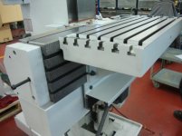
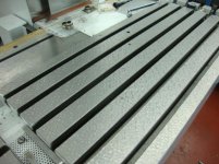
Pic's Top square cut static flaking, Bottom - ground surface, no flaking Both MFG are considered precision builders.

DSC02979.jpgDSC02978.jpg
 

Attachments

  • DSC02982.jpg
    DSC02982.jpg
    33.4 KB · Views: 779
  • DSC02980.jpg
    DSC02980.jpg
    46 KB · Views: 891
Hi all,

Thank you all for your illumination of the Moore approach. I always wondered
about this issue.

Richard, I assume that you flake the mating unexposed way, or did I assume incorrectly?

Another conundrum I've always wondered about is: why does deeper pin-pointing make
the machine last longer that more shallow cuts.? Is it because it has the ability
to carry more oil? I got the "deeper pin-pointing", from different books - it may not
be true, for all I know. The more shallow cuts would provide more bearing surface
and less loading per sq. inch.

Oh, will the questions never end - I hope the answers never do.
 
Yes I 1/2 flake the unexposed surface. Think about you have a big work bench that weights 500 pounds. Would it be easier to lift it for 2 men or 10 men? The same goes for the number of points per sq. inch. The more points the less weight per point and it lasts longer. That's why you can see a Moore, Pratt & Whitney, Sip, etc. Jig Bores that are 60 years old and they look like new. They were scraped to 40 points PPI. Rich
 
Rich, not disagreeing with you but if I follow the logic it would more nearly be the percentage of contact rather than PPI exactly. Generally we'd expect more points to correlate with more area, but one could hypothesize about a surface that had a lot of points of contact that were only pinpoints in size with lots of space in between. The actual weight (or force) divided by area of contact should be exactly pounds per square inch. And then a smaller pressure on the wear surface translating into longer life.
 
Rich, not disagreeing with you but if I follow the logic it would more nearly be the percentage of contact rather than PPI exactly. Generally we'd expect more points to correlate with more area, but one could hypothesize about a surface that had a lot of points of contact that were only pinpoints in size with lots of space in between. The actual weight (or force) divided by area of contact should be exactly pounds per square inch. And then a smaller pressure on the wear surface translating into longer life.

Good thought, Rich covers that in his scraping pamphlet. I don't have it in front of me but ideally you should have 50% contact area.

Its not to difficult to get 40 PPI, the hard part is getting 50% contact.
 
TG took the class too so he knows and never mentioned his opinion during the class...odd? He has a booklet too. I say 40 PPI and 40 to 60% contact. (the chart I provide was originally prepared by Sip and given to Biax and then to DAPRA) The low areas hold the oil. I have taught this to PHD's and they never said I was wrong. As DR. Alex Slocum once told me after attending my presentation at SME / IMTS in Chicago and he reviewed the same material and he never mentioned I was wrong. He did tell me there are many variables one needs to consider on machine tool ways and there is no calculation that is good for everyone because of load, size of the ways, speed, etc. But the rule of thumb is what I said and show in the booklet about the more points the less weight each point carries. Rich

PS: http://meche.mit.edu/documents/slocum_CV.pdf
 
Richard, thinking about what you are saying made me think of the ideal slideways, they are reasonably priced (Based on man hours invested) acceptably aligned to a published standard, hold that alignment under pressure through years of useage, and in addition they slide when needed without sticking.

Two imaginary sliding surfaces with such perfection that full contact and absolute flatness, (Hey, sounds more like a gage blocks). The only way these imaginary slides could work would be if they had pressurized lube 24/7. Otherwise they would wring.
So, for accuracy and alignment (It seems to me) a machines slideways are near the ragged edge of not even being useful as they approach perfection.

So, you want points per inch plus a certain percentage of contact. How do you judge the percentage of contact?
Thanks,


TG took the class too so he knows and never mentioned his opinion during the class...odd? He has a booklet too. I say 40 PPI and 40 to 60% contact. (the chart I provide was originally prepared by Sip and given to Biax and then to DAPRA) The low areas hold the oil. I have taught this to PHD's and they never said I was wrong. As DR. Alex Slocum once told me after attending my presentation at SME / IMTS in Chicago and he reviewed the same material and he never mentioned I was wrong. He did tell me there are many variables one needs to consider on machine tool ways and there is no calculation that is good for everyone because of load, size of the ways, speed, etc. But the rule of thumb is what I said and show in the booklet about the more points the less weight each point carries. Rich

PS: Page not found | MIT Department of Mechanical Engineering
 
I eyeball it, I have never did a scientific study and measured it with a caliber, some other ambitious person can do that. I suppose one could scribe lines making squares on a piece of plexiglass and calculate it more accurately. But i am not into the scientific side of it, just the mechanical side of it. I can see a Sheldon Cooper type person doing it. :-) In a perfect world you would have the same size square cut low spot next to a same size square high spot.

You should read about air bearings: Much of what I teach and lecture about is from information I have discussed with The Arneson Brothers at Professional Instruments (My Dad and I had been scraping machines for them them for years, plus I taught their guys to use the BIAX after some had worked with Moore scraping Moore testers)) before I was asked to speak at the IMTS / SME show in Chicago several years ago. I was all shook up when I heard Professors were going to be in the audience. I went over to Professional Instruments and they told me about The rotation of points and the Kinemedic Mount Principle. I had always known them as "hinge" and 3 points. But I wanted to impress the professors.

I am a simple man who is a Tradesman, i don't go into the depth of the "whys and how comes", I leave that to the scientists to think about. I just know how to scrape ways and use wearstrips to the best advantage in machine tool rebuilding and building.

It must work and be correct as I keep getting asked to teach at professional machine builders world wide. They have PHD's that understand one needs to take baby steps in all of this before they can run. I am a simple man as my dad was and not a college educated engineer or scientist. But they ask me to show them how the tradesman of old did his craft.

Years ago Cincinnati tried to eliminate scraping and used ground and slotted plates to get 50% on their Versa Power machines that failed miserably as the slots acted like a files and wore away the hardened ways it rode on. Times change and new technologies come along like linear ways, but at Quaser Machine in Taiwan..??????????.. they build super precision linear guide way machines but they still scrape the mount surfaces after the are precision milled and ground first. Also scrape the ball screw mounts and under the column to get precision alignment to the table. I taught scraping classes there back in 2010.

You can read more about the other side of what I teach: at these sites They have tons of reference material Sheldon Cooper would love to read.
Bearing Analysis | Professional Instruments Company and Here is Drew DeVitt's company where he first experimented with Moglice to make air bearings. NEWWAY Air bearings | Frictionless Motion

Enjoy, Rich

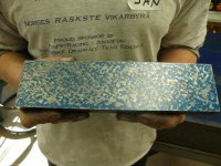
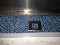
Pictures: L to R ; My assistant teacher Ted (masters degree in Engineering) at PMC, Precision Research Institute in Taichung Taiwan experimenting and testing on scraping 50% - 20 PPI on Turcite . Using the BIAX 1" Square Control Gage to count and eyeball measure the percentage of contact. Square cut scraping on Machine in Germany at my recent class at a Machine Rebuilder.

IMG_1407.jpgIMG_0572 (1).jpgIMAG0613 (1).jpgDSC02979.jpg


Back
Top