What's new
What's new

Gibbs design and implementation

Elitebook

Plastic
Joined
Mar 22, 2018
I'm not sure if this is the correct forum section however I believe members with potentially the most knowledge about the subject hangs here :)

I'm making a few sketches for a small 3-4hp toolroom lathe with about ø150x400mm capacity between centers.
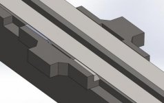
The bed is 200mm wide and has 30° taper on each 25x75mm rail. Carriage is guided by the top of the rails and the outer tapered edges. Tail stock is guided by the top of the rails and the inner edges.

The carriage is 400mm long and I plan to use 125mm long 1° tapered gibs, one in each end of the carriage. The gibs adjustment mechanism is still not implemented.

Questions;
- 1° taper and 125mm length in the ballpark for this kind of application?
- Will it for some reason be problematic to use two gibs instead of one?
- Other suggestions?

Thanks! :)
1.jpg2.jpg3.jpg
 
My twopence is like Irishman's reply on being asked for directions by a visitor. " Well I wouldn't start from here if I was you ". Why re-invent the wheel ?

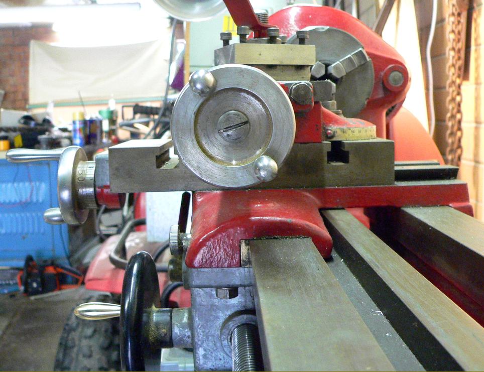
If I was making a lathe bed I'd keep it simple. Two equal flat ways first of all. No fancy angles to grind or mill. Easy for the layman to " Shamban " or " Turcite " the saddle. I'd have the saddle running on the " narrow guide " principle to minimise yawing. So the saddle would be located longitudinally on the front shear. The saddle would have a " fast " face that fitted up to the inside face of the front bed shear. The " loose " face would have a long tapered gib that fitted up to the front face of the front shear. The head end of the tapered gib would be at the tailstock end of the saddle.

The saddle would be held down by two " keeper strips " that are fitted to be a " running fit " to the underside of the outer edges of the ways. All easy to do machining procedures.

The tail stock will be located by running on the inside edges of the bed ways. You could either fit the tailstock closely or use a gib. You can use simple clamping mechanisms to fasten the tailstock in place.

Regards Tyrone.
 
The saddle would be held down by two " keeper strips " that are fitted to be a " running fit " to the underside of the outer edges of the ways. All easy to do machining procedures.

So basically like this?
Brass_gibs.jpg


My first sketches was box-way design however I discarded it due to needing a total of three gibs to lock the carriage in all planes. If I have understood your proposal correctly you are suggesting to replace two of the gibs keeping the carriage in vertical direction with close fitting keeper strips on the underside of the rails.

It will probably be sufficient for what I'm trying to achieve here. If the carriage lifts vertically 0,1mm it will theoretically change a 10mm turning diameter with 0,002mm. Since I have stacked the carriage and cross slide with the same rail system I can double the numbers, but in the real world, for my application, it will be negligible. Also the load of the carriage will keep it down together with the cutting forces unless turning with upside down oriented tools to keep the chips falling downwards.

I'd have the saddle running on the " narrow guide " principle to minimise yawing. So the saddle would be located longitudinally on the front shear. The saddle would have a " fast " face that fitted up to the inside face of the front bed shear. The " loose " face would have a long tapered gib that fitted up to the front face of the front shear. The head end of the tapered gib would be at the tailstock end of the saddle.
Regards Tyrone.

About "yawing", I'm guessing that this is an issue when the feed rod is located as on a conventional lathe?
My preliminary plan is to locate the lead screw down between the rails so if the cutting forces are neglected (since it will depend on the position of the cross slide) the nut is in the dead center of the carriage (when viewing the lathe from above).

Regarding the "narrow guide" principle.
The image below reflect your above post?
img32.jpg
 
Hi,

In short I concur with Tyrone. But I am Not the one to shoot down a project :)

But what you are showing is anyway very similar to old designs you can find in the connelly book, and a common gib type for it is referred to as a Angular Flat Gib.
Basically there is an angle inwards (as you have) and a smaller angle/draft outwards and then you pull it up, proper fitting required.

I must say I have nill practical hands on experience with this Gib type myself and I am at heart a bit hesitant of the application lathe sadle but that is 100% un-founded. I do recall seeing this type of gib used in milling machines, in the vertical guide where it is in shape of a dovetail.

I think, unless you have a novel design to try out, ride on the shoulders of time tested designs and choose one that suits your workshop/budget capabilities, assuming you will build it yourself in home workshop.

And in my opinion don´t worry about lift, the keeper strips should anyway be fitted to a gap of 0,01-0,02mm. This much gap (ballpark) you will need in this dovetail design as well, perpendiculaly/space between surfaces, for proper sliding and lubrication. This actually means that your vertical composant (gap) is much greater than in a boxway design.
Personally I prefer to work in the direction that things are pressed together during operation rather than lifted apart.
 
So basically like this?
Brass_gibs.jpg


My first sketches was box-way design however I discarded it due to needing a total of three gibs to lock the carriage in all planes. If I have understood your proposal correctly you are suggesting to replace two of the gibs keeping the carriage in vertical direction with close fitting keeper strips on the underside of the rails.

It will probably be sufficient for what I'm trying to achieve here. If the carriage lifts vertically 0,1mm it will theoretically change a 10mm turning diameter with 0,002mm. Since I have stacked the carriage and cross slide with the same rail system I can double the numbers, but in the real world, for my application, it will be negligible. Also the load of the carriage will keep it down together with the cutting forces unless turning with upside down oriented tools to keep the chips falling downwards.


About "yawing", I'm guessing that this is an issue when the feed rod is located as on a conventional lathe?
My preliminary plan is to locate the lead screw down between the rails so if the cutting forces are neglected (since it will depend on the position of the cross slide) the nut is in the dead center of the carriage (when viewing the lathe from above).

Regarding the "narrow guide" principle.
The image below reflect your above post?
img32.jpg

Yes the keeper strips in the first photo are what I had in mind only not as clumsily fashioned. You need 0.001" to 0.002" running clearance. The cutting forces are mainly down on the saddle so you can afford a slight amount of clearance.

The lathe in the second photo is a good example of the " narrow guide " principle. The motion on that lathe is provided by the rack and pinion for longitudinal feeding and the lead screw for threading, both are positioned as close as possible to the " narrow guide " . That's the ideal position to minimise " yawing ".

The design you suggested with the tapered faced keeper strips in reality can be a pain to adjust.

I've done a lot of work on Hor Bores and some had the narrow guide principle design and some had the lead screw in the middle of the ways as you suggested. Hor bores only have a leadscrew to provide longitudinal motion. The " fast " face is on one inside face of the ways and the " loose " face with the gib is on the other inside face. The keeper strips are just the same, they go under the lip of the ways on the outside. This works equally well but obviously there is no provision for a rack and pinion.

Regards Tyrone.
 
Thanks for the input! :)

Yes the keeper strips in the first photo are what I had in mind only not as clumsily fashioned.

Do you have a less clumsy example I can have a look at? 🙂

I have sketched a version with the narrow guide principle and from what I can figure out the front rail must be quite narrow (50mm width front rail and 100mm width rear) to keep the 200mm total bed width and to retain sufficient support for the tailstock base (quill center will be offset with this design). I also want to avoid machining the underside horisontal face of the bed surfaces in the middle since it complicates the whole build.
4.jpg


Back
Top