What's new
What's new

LeBlond No 1 Surface/Tool and Cutter grinder

becomingguru

Plastic
Joined
Nov 6, 2014
Location
Pittsburgh
Greetings all. Not sure how interesting any particular project of mine might be to others, but thought I'd offer my other current project, a LeBlond grinder. I picked this up last winter and spent the next several months scraping the ways, spent some time figuring out how to get a motor to power a headstock which was previously belt driven from the ceiling, and am now turning my attention to scraping the headstock. I would like to get a unified lubrication system on it at some point (it currently has a bunch of holes with caps for oil), and I haven't put any flaking on the ways yet, but it's not a high-use item, so we'll see.

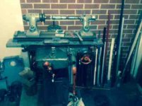
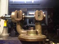
Here are two pictures of the tool from straight-on and at angle. Headstock is on the bench, and conspicuously missing from the top of the column. That's the spindle held between those centers. Didn't really want to set it on anything after getting it back from having it ground :)

ImageUploadedByTapatalk1444173940.610054.jpg ImageUploadedByTapatalk1444173950.640337.jpg

Here are a few pictures of the bearings inside the headstock. I'm two or three cycles into scraping the bearings. The split in the bearing is up.

Here's the smaller bearing at about 0.8" diameter and maybe 2" length.

ImageUploadedByTapatalk1444173974.915951.jpg

And two of the larger bearing, at 1.08" diameter and maybe 2" length.
ImageUploadedByTapatalk1444173989.185794.jpg ImageUploadedByTapatalk1444173998.705221.jpg
 
Last edited:
Here I have the headstock mounted to a harbor freight anvil which I'm in the process of scraping to use as a lapping surface.

The spindle is not in the operational position, which would have the shoulder within the body of the support - that is, moved to the right about 2". I just set it in there to show position. I've already marked the inside and didn't want to reinsert it.

ImageUploadedByTapatalk1444174312.442332.jpg ImageUploadedByTapatalk1444174322.021576.jpg
 
Last edited:
I was looking for a manual to look for the bearings and found to threads on them:
http://www.practicalmachinist.com/vb/antique-machinery-history/help-me-leblond-no-1-mill-188447/

http://www.practicalmachinist.com/vb/general-archive/old-leblond-tool-grinder-85535/

Remember the 1/2 moon flaking averages .002 deep so I recommend you do not flake a exposed way, but a hidden way or the bottom of the head-stock. I generally grind the swivel plate and leave it that way. If you have it scraped, then just leave scraped or square cut the scraped surface or give it the checkerboard look after you have it scraped for a uniform look as scraping averages .0002" deep and less likely to pull some grinding grit under the head if grit fills a .002" low spot.

Please show the bearing and you ID scraper and what the high-spots look like.

Rich
 
You guys made my day and cleared up a mystery! I bought what I thought was a KO Lee tool and cutter grinder several years ago. I have been searching forever trying to find out the model number. There were no tags on the base and it was missing the door.

Looks like it actually was a LeBlond #1 with a KO grinder head attached to the column. I have it torn down to be painted and scraped after attending Richard's class in NC. The grinder head is mounted on a slide with gib that does not look like it was put together in a shop. Is there any chance that KO Lee worked with LeBlond or made parts to fit the LeBlond columns? Any discussion on how you approached scraping the column, knee and saddle would be most appreciated. The saddle, especially because the ways are enclosed by the casting.
Walt B
 
Glad the post was of value then :)

On scraping: The cast-in-place ways inside the saddle are a bitch, yes. Where does one find a straight edge of the perfect length for such a thing? So, I scraped the bottom of the saddle gib flat and used it as a reference for the saddle ways. I used the same gib as the pattern for the sides of the column ways.

For the column, I set my granite flat on the edge of the table, removed the knee screw from the column, and let the base of the column hang over the table to get a rubbing on the two coplanar ways. It took me some time to figure out how to get the screw out. This machine seems to be entirely held together with taper pins - drilled by hand. I conclude this because the alignment on the pins is all over the place. Like so many old machines, somebody sprayed it down with paint before selling it, so I had to scrape a bunch of paint and gunk off to find the pin. I think I then used the afore-mentioned gib from the saddle to mark the outside ways. Also, it was problematic to get the reference flat on the ways, since the casting wasn't too clean. So I used an angle grinder to grind back the inner corner of the intersection of the ways with the round part of the column to make a flat surface to mark against.

For the knee, I removed the gib from the knee and used the three scraped surfaces on the column to mark and scrape the knee. I confirmed the alignment of the knee in the column by sliding the knee up and down in the column with an indicator against the exposed fourth way. Don't remember if I had to adjust geometry to get it aligned. Then, I held the knee gib in place against the knee to get an in-situ rubbing on it from the last way surface on the column.

I then scraped the two coplanar ways on the top of the knee, marking it directly on the granite flat. I repeated marking the other two surfaces of the top knee ways with the gib from the saddle and scraped them flat at whatever angle they were at. I set the saddle upside down on the table and followed the same process for marking the bottom of the saddle with the three scraped ways on the knee, and did the same with checking alignment and marking the gib in situ against the fourth way.

On the table, I marked the bottom of the table on the plate and used it to mark the top of the saddle. I haven't done the dovetails on the table yet, since I lack a camel back. Probably buying one of them from Richard next month (unless someone else has a used one they'd like to part with), at which point they will get scraped.
 
On the bearings, I meant to be posting pictures of the spotting in them. Here are some more pics after another cycle:

Here are some from the smaller bearing:
ImageUploadedByTapatalk1444249625.621713.jpg ImageUploadedByTapatalk1444249646.479523.jpg

And from the larger bearing:
ImageUploadedByTapatalk1444249654.361275.jpg ImageUploadedByTapatalk1444249663.706881.jpg
 
I recommend you do not flake a exposed way, but a hidden way or the bottom of the head-stock.

Richard, thanks for the follow-up advice on where to put the flaking. I've taken to heart your various admonishments for putting it on hidden surfaces to keep the gunk out and will plan to do that - after I develop some skill at it. Haven't given it any practice yet.

And thanks for the links. The structure of that mill looks quite similar to what I've got, though the saddle casting seems to be a little different.

I had found the other thread you posted when I was poking around deciding whether or not to buy it. There's another one somewhere on here or homeshopmachinist which dates the machine at around 1912, and several posters on that forum seemed to think it was only worth scrap. I feel sure I shall get my $300 (including shipping) out of it, if only to practice scraping :)
 
I bought a box of hand scrapers a few yeara ago that came from a Navy Ordinance shop and inside it was a small pull scraper made out of a 1/4" tool steel bar and on the end was a short L shaped hook. I figure it was for pull scraping inside small bearings like yours. I have a set of spoon scrapers like you have and scraped bearings for years like your doing, until a Bliss Punch Press Tech I helped at GE in Mpls. He introduced me to Time-Savers lapping compound and I started to lap the bronze bearing before i scraped oil pockets into them. The name is perfect as the time it saves is amazing. It has been around for years and it won't embed. They used to have study'd done by the US Navy that documented that it won't embed.

Another tip when scraping a round bearing like that is to scrape 3 lower areas so you get 3 pads. You can see where it is worn now, so those should be the higher pads. A famous grinder uses 3 pad shoes the Cincinnatti Centerless Grinder has 3 Babbitt bearings that these heavy duty machines run on. The 3 lower areas act as oil puddles too along with the oil grooves. Rich

PS how narrow are the ways?

Timesaver Lapping Compound Yellow Label and Green Label Compounds, non imbedding lapping compound, manufactured by Micro Surface
 
I had thought of lapping it as well. Did some poking around and found this thread http://www.practicalmachinist.com/vb/general/lapping-phosphor-bronze-bushing-164839/, in which Forrest seems to offer great caution about this. The same compound is mentioned therein. He mentions having a setup to maintain proper positioning during lapping. His words promoted enough concern, that I had simply gone about scraping it.

I would think that I could, easily enough, support everything between centers and do the lapping thing. Is there any special process to doing it? Special alignment apparati, etc?

Not sure about what you mean by narrowness of the ways. Each flat on the column is about an inch wide and maybe 18" long. The contact portion of the ways on the saddle are about the same. The table is probably 30" long with 3/4" tall dovetails. The dovetails on the column and knee are 45 degree, while those on the table are like 70 degrees.

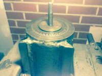
This was my first time to see ways like this on the column. here's one of the top of the column and it's ways.
ImageUploadedByTapatalk1444261916.934204.jpg

On the multi-contact surface bearing, I found reference to this in Nick Mueller's video https://www.youtube.com/watch?v=iJd8Zwd9L1k and was planning on doing that when I get that far.

This is my first bearing to scrape.
 

Attachments

  • ImageUploadedByTapatalk1444261707.762169.jpg
    ImageUploadedByTapatalk1444261707.762169.jpg
    16.7 KB · Views: 166
Becommingguru,
I need to read your description more thoroughly and think about your approach. Richard, the ways are about an inch wide and the gib for the saddle bolts on from the bottom. There are 2 tapered gibs for the table. I will take some pictures of the individual parts. Is there an archive on posting photos?
WB
 
I have used Timesaver compound for over 30 years ad have never had issues. Like I said Bliss Press uses it. I would not recommend it if I didn't think it would work. This booklet is from the Time-saver site and give you a lot of info.http://www.newmantools.com/lapping/timesaver_booklet.pdf.

It was nice to see Nick uses the 3 pads like I have been writing about for years. GMTA. Like I said I have used the spoon scraper like the one you and he show, but you need to test the small radius pull scraper like I described to really see how much easier it is to use plus it is a lot easier on your wrists plus the low spot depth is so much deeper, I'll see if I can find it and take a pic. the hook is radius looks like a U------handle ----> pull.

You wrote in post 6 about the table ways.
"On scraping: The cast-in-place ways inside the saddle are a bitch, yes. Where does one find a straight edge of the perfect length for such a thing? So, I scraped the bottom of the saddle gib flat and used it as a reference for the saddle ways. I used the same gib as the pattern for the sides of the column ways.
I was curious what you meant by "cast-in-place" ways and what size they were as I have a 24" long x 3/4" wide camel back straight-edge I made to scrape Brown & Sharpe grinders that use roller bearings and if it was close, I could lend it to you and possibly Walt.
A few pictures of the column ways and I can help you figure out he best and fastest way to scrape them. Rich
 
Post 9 of the mill thread shows the grinder. http://www.practicalmachinist.com/vb/antique-machinery-history/help-me-leblond-no-1-mill-188447/ From the picture I am wondering where the pulley mounts in the center of the spindle on the wheel head, is that straight or mike's the same? If it is you can scrape the bottom parallel to the top of that. As I show in the last picture I made that straight surface of the spindle parallel to the table top.

If not you could borrow or buy a test bar that would fit in the taper center hole.

That is how I lined up the heads on the Myford, Drake and Studer grinder heads I rebuild.
2014-03-06_17-19-37_155.jpg2014-03-06_15-06-52_927.jpg2014-03-06_15-09-21_788.jpg2014-02-27_17-27-11_897.jpg
 
It just dawned on me you want to scrape the column next. That's bass ackwards. Rebuilding is like building a house, you start at the bottom and work up. So if I were rebuilding the machine I would scrape the table / bed ways like have done then column ways and then the wheel head, then the head and tail-stocks. You can prepare scrape the wheel head as you are doing then match fit it to the top of the column scraping your final alignments. If I were you I would look for a small granite plate and use your anvil for forging. Rich
 
Last edited:
Richard, I didn't mean to be challenging your claim on the time saver compound - was just looking for a clarification between the experiences of two experienced people. I do have a mental picture which comes up from your description on the pull scraper. Here's a crude sketch of what comes to mind:

ImageUploadedByTapatalk1444508824.026954.jpg

And yeah, it seems that the cutting depth with the spoon scraper isn't terribly great.

In speaking about ways on the underside of the saddle, I wonder if I demonstrated an opinion I no longer have. I think I found them to be a real pain when I was doing them just because of my lack of experience. I was annoyed that they were 45 degrees and I couldn't get the prism I had scraped at 60 degrees, and they're buried in the casting so the length of the straight-edge you can use is limited. I now know that 45 degrees is common, and many straight edges (like yours) come with 45 degrees, for good reason. I also had, at the time, the belief that you needed a reference as long as the thing you're scraping, which I also now know to not be true. Perhaps I complained about them too strongly without consideration for knowledge I've gained since then.

Here are two pics of the underside of the front of the saddle. You can see the knee on the left, and about 6 inches of female dovetail above the bell/shaped mechanism below. The lip which runs along the top of the bell-housing runs around to the right, coming toward the camera, and prevents a long straight-edge from being used to mark the female dovetail.

ImageUploadedByTapatalk1444508858.246352.jpg ImageUploadedByTapatalk1444508874.897441.jpg

And here's one from the rear of the same casting. The column is on the right.

ImageUploadedByTapatalk1444508891.316440.jpg

I do very much appreciate the offer of the loan of one of your straight-edges. I may not take you up on it just yet, though. I'm hopeful to be able to buy one in the near future. Though, If you were the one who scraped it, I would like very much just to see its work surface, just to see what I could learn from looking. I have a borrowed Brown and Sharpe straight edge, which I have had since early on in my cultivating scraping skill, and studying the scraped surface broadened my idea of scraping.

On aligning the spindle to the ways, there is a cylindrical surface on the spindle, colinear with the two bearing surfaces, which I expect to be a good reference for setting the bottom of the headstock. I haven't checked it for roundness yet, though.

You mentioned scraping the column next. Didn't know if you meant that for me or Tiaw. I had to take the grinder apart to get it into my shop, and I scraped it as I put it together: column, knee, saddle, table (half of the table), in that order.

Thanks again for all your help. I'll get some more pictures up of the bearing as it gets closer.

Oh, and on the anvil - it's too soft. Unless the work is orange-hot, it leaves terrible marks in the anvil. While it's made of some of the hardest cast iron I've scraped, it's not hardened, and got all dinged up when I tried to use it. I since replaced it with an old 200lb Hay Budden - well worn, but solid.
 
Tiaw, considering the way that I scraped the grinder the first time, the big reason I used the saddle gib as a reference was that I simply had no straight edge of the proper length and angle.
 
VetteBob, thanks for the link for the time saver compound. I'm shocked at how cheap it is, considering the claims it makes. We'll see whether it arrives in the mail before I finish scraping the bearing :P
 
Column2.jpg

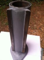
Since my grinder is completely disassembled, I need to get some pictures posted that might shed some light on the saddle ways. It will take an angle bar 18" long to print the 45 degree way. Bear with me in posting photos, this is a learning experience. The photos of the column as a test. OK, that looked like it worked, now to get something more pertinent.


Back
Top