What's new
What's new

precision lapping of machine and instruments

CBlair

Diamond
Joined
Sep 23, 2002
Location
Lawrenceville GA USA
Here is another video in Japanese, it shows some precision lapping used by Mitutoyo in finishing some of its precision gages. While this is a long video you can see he is using some sort of ceramic square to lap the surfaces as well as some of the equipment used to check the squares they are also lapping. We may not use these techniques for machine tools but as we might use these gages to check our machines while we are scraping them I thought I would share it with you.

Does anyone know more about the ceramic square he is using to lap with or does anyone speak enough Japanese to help us understand anything more interesting in the video?

?????????"??"?????????????????????????????????????????? - YouTube

Charles
 
I've long enveighed against "lapping" as expressed on home shop fora like HSM, PM and others where a machine tool shows wear so the owner's naive solution is to lap the worn parts together as though somehow more uncotnrolled wear woild self-correct. Never, ever happen. Look at this video of Mitutoyo techs of vast experience who have every inspection aid known to man on hand for "inspecting in" accuracy and geometry.

Lapping done right is controlled localized corrective wear. Lapping done wrong is compounding wear. Any of you desiring to lap any part of their machine tools should look closely at this video. While the work shown is maybe 10X as accurate as needed in a manual machine tool the atention to detail and care with heat and cleanliness is roughly the same.

I'm only speculating here but I suspect the laps used in this vid are cast iron and the lapping compound is possibly levigated alumina perhaps 10,000 grit or 1 micron abrasive size. Ceramic as I understand the materials I've seen makes a poor lap. Its energy of rupture is too low and it has practicaly zero embedability, an essential attribute for a lap. Typically the lap is considerably softer than the material to be lapped. The abrasive grains have to embed themselves in the lap's surface to form temporary cutting edges, one of thousands or millions in the laps working surface. Each edge makes a little scratch or furrow in the work and plows out tiny particles of swarf. Then it rolls to a new position to embed and scratch again and so on until it escapes at the work edge. So it's the softer material that does the cutting and the harder material that gives up the swarf.

I've seen many posts where abrasive on glass is offered as the standard of lapping accuracy and efficiency. Even the hard and strongest glass is preferentially lapped compared to the much more durable but softer cast iron or steel.

I bitterly regret there were no English sub-titles in the video. Most of the gents making their points were older and had years of experience and de-facto company culture to disclose. They could have taught me - us - a lot. The best I could do was take in what I could, replay parts and re-think what I saw hoping repetition and visual cues cwould translate wisdom in a foreigh language to something I could understand.
 
Last edited:
That is an interesting point Forrest, the idea of cast iron makes a lot of sense. I dont know why I thought of ceramic laps but probably because I had seen some ceramic forms like they were using and I know they were made very accurately. However your description of why that wouldnt be desirable sounds right to me. It also seems obvious that they were using iron plates to lap the smaller parts on.

They did have a pretty neat instrument to check the large squares they were working on. It appeared to be a linear slide but it was balanced with another one on the back side of the tower. I am assuming that was to balance the load and not let the tower bend but I could be wrong. I am sure when you measure to the tolerances they were working to there are a lot of things you have to do differently than we are used to.

Yes it is a shame we dont have some translation, I may have a chance to get some translation done but the person is on the way to vacation. There are several videos I have come across in the last couple of years that I would like to get translations on. Some I have posted here already and some are waiting in the wings. If anyone knows someone who can translate for us it would be nice to share.

Those brown bars the man was lapping, do you think those are parts for a CMM or does anyone recognize what they are?

Charles
 
CBlair, thank you for posting this video. I too wish for a translation, for this vid and several others from the same channel about the same subjects. I don't know any one Japanese. I wonder if there is a pc program or google magic that could make this happen?:drool5:
 
I'm pretty sure there is a PM member (probably more than one) who could translate but I can't remember who ,it would be interesting to at least have some idea of what is being said.
 
I am putting an add on CL for a translator. What would be a good media form to get the information down. preferably a video voice over but that could get complicated. Maybe just a typed format and we would have to guess the at the time frame.
 
I too believe hand lapping is a lost art and it can get you into trouble real fast. I have tried it a few times and if your not real careful the shorter part can get high in the middle like the bottom of a rocking chair. Years ago as an when my brother and I were apprentice's every so often we would get the job of lapping 3 12" x 12" lapping plates. In the shop we used to lap parts on them, and it took a learning curve and lots of muscle to do them.

I hated that job.. ( I got all the crap jobs back then, as all Journeymen know how it goes, ha ha). It was easy when I started with the Coarse Clover Compound but as they got flatter and we switched to the finer Clover we got more friction. Recently I have had 2 students tell me how they "hand lap" their scraper blades on a flat diamond lap (looks like a sharpening stone) and how good it worked. When they tried my Glendo to sharpen their blade, they looked at me as if it was magic how much better it cut then the hand lap. One actually threw his lap in the trash can....

Lapping Precision parts as shown in the you Tube clip is a "trade" and unless your taught or have lots of time on your hand I would avoid it.

All of us has probably laid some fine emery cloth on a flat plate to flatten a part of de-burr it and discovered if your not careful, you can screw it up fast too. Rich
 
Yes Richard, not too many of us would have the need to lap parts or tools, not in the way as shown on the video. But that I why I posted it, just to give an idea of some of the work that goes on behind the scenes of tool making. I am still waiting to find out if the brown bar he was working on was part of a CMM or some kind of master. There was a little video showing the inspection of a master square, I was hoping for more about that. The other part the old guys were working on is I think part of the electronic height gages that Mitutoyo makes. It also appeared there was some video of what appeared to be the bed of another machine with double vee ways. I wonder if that was for some kind of measuring machine?

Lots of questions and few answers, but I still hope some of you found it interesting.

Charles
 
I can ask my friends at PMC to see if they can translate it for us. Many of them speak and read many languages. I feel stupid when I am over there. The Chinese and I bet the Japanese read and write with 5000 charactures. I always say I have issues writing English let alone another language....LOL
Yes it is fun looking at so many things on You Tube.....Almost better then reading a Popular Mechanic Magazine of old. :-) Rich
 
......i have lapped the slots of titanium bars assembled together so a multi layered liquid flow of chemical pours on to paper moving at 1800 feet per minute. the pouring lip also is a precise almost knife edge shape.
....... we used a computerized capacitance gage the would probe slots and we could have a full size printout 6 foot long pieces of paper showing slot width to millions of a inch it magnified error so we could easily see millionths errors..
........basically we used flat blocks with stones clamped on or 400 to 600 grit sandpaper stuck to it. of course the full size graph printout showed how much to lap and after you remeasure after a few times you get an ideal how much needs to be done. we had to wipe the bars with alcohol and let dry in a air filtered temperature controlled clean room. we used rubber gloves as finger prints on the bars would create errors in the slot widths of many millionths of an inch
........ the pouring lip was cut with a shaper / planer or mill and always finished with special stone or abrasive paper holders to help get precise angle and shape needed for pouring lip. we then would take 2 part silicone rubber and put on spots along pouring lip and let cure. section them and put sections on a digital camera inspection device that was at least 30x magnification. on the computer screen you could check rubber edges and measure angles and widths of precise pouring lip against drawing. not a chance in the world it could be scraped. errors of .001" would easily wreck or disturb the pouring of the seven chemical layers
........ the seven layers of chemicals would smoothly pour over what looked like a water fall on to paper moving 1800 feet per minute giving 7 even layers on the paper parallel to millions of an inch. any error in slot widths or pouring lip would create waves that would wreck how even the 7 liquid layers poured on the moving paper.
....... of course this needed equipment that measured the lapping and magnifying and measuring the lapped surfaces.
.
the technology is so rare that when the Chinese government ended a partnership with a Japanese company and formed a new partnership with a American company we had some Japanese equipment sent to the USA to take apart and study to compare how we did things and how our competition did it.
........ needless to say we were always worried if the Chinese decided to end our partnership our American equipment might be sent to Japan to study.
 
DMF_TomB, I'll bet you worked on my Acetate casting hoppers as well. I was always impressed with the quality of the work that came out of the shops. Once I retired, I started doing some metalworking myself, and I am now totally in awe of the quality of work that I was privileged to use. Thank you!
 
DMF_TomB, I'll bet you worked on my Acetate casting hoppers as well. I was always impressed with the quality of the work that came out of the shops. Once I retired, I started doing some metalworking myself, and I am now totally in awe of the quality of work that I was privileged to use. Thank you!
.
i got laid off in 2012 when they closed bld 319. in 2005 when they shut down bld 52 i had to crush / destroy critical coating equipment to make it unusable. a government requirement for writing off the destroyed equipment. kind of sad to see very expensive one of a kind equipment destroyed and put in the scrap lugger
.
i work for Gleason now making cnc gear cutting machines
 
Charles I am going to have a 36 x 48" Pink Granite table grade A lapped to a AAA Grade later this fall and The fellow who will do it I am sure will let me film the job and after he does I am going to have my son who is an computer expert help he put it on You-Tube. Rich
 
Charles I am going to have a 36 x 48" Pink Granite table grade A lapped to a AAA Grade later this fall and The fellow who will do it I am sure will let me film the job and after he does I am going to have my son who is an computer expert help he put it on You-Tube. Rich

That would be nice, thanks.

Charles
 
Charles I am going to have a 36 x 48" Pink Granite table grade A lapped to a AAA Grade later this fall and The fellow who will do it I am sure will let me film the job and after he does I am going to have my son who is an computer expert help he put it on You-Tube. Rich

THAT I want to see. Upgrade an A plate to AAA. All of it. Show and tell the equipment, the initial checks, the map, the lapping strategy, discussion of lapping media, process checks, the inspection and acceptance, and the final results.

Here's the best I found:https://www.youtube.com/watch?v=NWObTpn6dTk

Make it a 1 hour industrial turotial instead of the typical 3 minute stoner gloss you see on "How It Works" .

Wow! AAA on a 36" x 48" plate. I looked at Fed Spec GGG-456-P and found no listing for AAA. Extrapolating grades and following the formula: the max flatness deviation would be 0.0001". My question: is the plate thick enough to pass the weight test in Fed Spes GGG-P-453 Para 3.2.3 deflecting only 1/2 tol tolerance center loaded to 50lb/ft^2. What's that work out to? 10" thick maybe? 12? I'm too lazy to work the deflection formula in the standard. You can always post a chart showing weight limitation Vs flatness spec.

Temperature gradient: Hoo, boy!!

Good luck
 
I saw this guy do it a few years ago when he demo'd doing it to a group of students who took a scraping class here in MN. The tech is a friend of the fellow who did the class. Several of the students took pictures and i believe movies. I will ask the host if he has pictures. Jeff Thiele, Rob Mueler, Greg Dermer and Peter Gobar who are members here, were in the class and they may possibly something now. I will email them and ask them.
The tech used a Rahn Repeat-o-Meter and Mahr Electronic Level conected to a lap-top. I will film what he shows me as I will be probably paying him by the hour. Maybe I can arrange it and you can come and watch him do it?. I have had Tru-Stone lap my granite straight-edges to that spec. It's expensive, but can be done. Rich

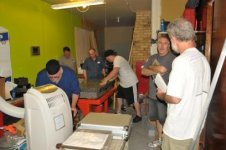
Peter the host took some still pictures and just sent them to me. There are about 12, but will do a few.. Rich
 

Attachments

  • DSC_2752.jpg
    DSC_2752.jpg
    19.8 KB · Views: 488
  • DSC_2774.jpg
    DSC_2774.jpg
    19.8 KB · Views: 1,332
  • DSC_2757.jpg
    DSC_2757.jpg
    19.8 KB · Views: 522
  • DSC_2758.jpg
    DSC_2758.jpg
    16.7 KB · Views: 476
More Pic's The pic of PC shows Grade B, but i would swear he said it was a A before he lapped it. Rich
 

Attachments

  • DSC_2755.jpg
    DSC_2755.jpg
    18.2 KB · Views: 547
  • DSC_2780.jpg
    DSC_2780.jpg
    20 KB · Views: 612
  • DSC_2759.jpg
    DSC_2759.jpg
    19.8 KB · Views: 464
  • DSC_2784.jpg
    DSC_2784.jpg
    11.8 KB · Views: 437
I saw this guy do it a few years ago when he demo'd doing it to a group of students who took a scraping class here in MN. The tech is a friend of the fellow who did the class. Several of the students took pictures and i believe movies. I will ask the host if he has pictures. Jeff Thiele, Rob Mueler, Greg Dermer and Peter Gobar who are members here, were in the class and they may possibly something now. I will email them and ask them.
The tech used a Rahn Repeat-o-Meter and Mahr Electronic Level conected to a lap-top. I will film what he shows me as I will be probably paying him by the hour. Maybe I can arrange it and you can come and watch him do it?. I have had Tru-Stone lap my granite straight-edges to that spec. It's expensive, but can be done. Rich

Peter the host took some still pictures and just sent them to me. There are about 12, but will do a few.. Rich
.
we got a mahr electronic level connected to laptop too for checking machined castings while still in the machine. they are very very touchy. i noticed it is better to slide them along surface. if you pick up and tilt the level sensor and put back down on same spot they do not always repeat for quite some time. maybe liquid in sensor moving around taking time to stop moving. definitely a technique just in using the electronic level. i believe it measures to 0.1 arc seconds. like i said a really very very sensitive level.
....... it is a tool we use to confirm our big cnc mill is not making a wavy surface instead of a flat surface
 
If anyone is interested, here's some details on some homemade optical flats made by a friend of mine as a bit of a personal challenge. Lapping glass has an advantage in that the material is transparent and optically reflective enough that the surfaces can be tested with simple home made optical apparatus. Forrest: the initial rough lapping is done with cast iron tools up to a certain point, then three discs are lapped against each other in a specific sequence of the disc A, B & C against each other with discs spending equal time on top and on the bottom with final optical polishing done with cerium oxide or red iron oxide. A polishing tool coated with pitch allows the abrasive charged polishing tool to be pressed against the optical surface so the the soft pitch will conform to the shape of the optical surface.

Testing of the surfaces involved letting the glass discs cool for several hours in the testing equipment after the last bit of lapping and then testing early in the morning to avoid vibrations cause by the street traffic going past.

So optical flats are within the reach of the amateur but there's a prodigious amount of patience and effort involved. In the photo below you can see two of the three discs placed one on top of the other with a tiny nylon shim at one side and illuminated with a sodium discharge lamp: the interference pattern formed accurately shows the combined error of both flats taken together of about one wavelength (the width of a dark and bright line in the image) down the bottom of the discs. The sodium vapour lamp wavelength is 589.3 nanometres or 0.0000232 thou so the combined error of the two optical flats is 0.000000232" (my math may be wrong there) at worst. Each flat's error can be deduced by comparing the interference fringes formed against the other two flats and counting the fringe pattern.

Lapping is more suited to making accurate shapes due to long term averaging of the lapping strokes and works best with simple geometric shapes like flats, spheres, sections of toroids (doughnuts) and cylinders. The hardest of all shapes to lap is a flat due to curves forming when the lapping tool overhangs the object being lapped and gravity pulls on the overhanging tool.


The image below has a black wire in the middle which is used to minimise parallax when viewing the fringes and to the left of the test equipment are the bottles of emergency homebrew apple cider. Website showing the methods used and the machines built is here: Astro-Tel - Flat Tester

attachment.php


Edit: The image shows a combined error of a half a wavelength, not one wavelength stated earlier, so the error of one of those 8" optical flats is of the order of 1/4 wavelength at the bottom edge or 147 nM.
 
Last edited:


Back
Top