What's new
What's new

Start Stop Push Button Control Switch Wiring - Please Help.

cg25713

Plastic
Joined
Aug 11, 2020
Hello All: I'm reconditioning a 14" South Bend drill press and I could really use some help with the re-wiring. Instead of a toggle switch it came with a Square D Company "Start" "Stop" push button controller. I'm somewhat new to this stuff so please excuse my ignorance.

There are four connections on the back of the switch and I have new positive, negative and ground wires running from the motor and new power cord. The ground wires I connected to the main casting. How are the positive and negative wires connected to this simple start stop switch. I tried variations but can't get it right.

Any guidance would be greatly appreciated. Thank you very much in advance.

Steve
cg25713
 
Do the wires go direct from switch to motor or is there a motor starter/contactor between the motor and the buttons. Pics will help a lot.
Is it 120v or 240v?
Where did the power cord go to?
 
A little impatient, are we?

Is your lathe motor 120VAC, 240VAC, or....?

Pics of the front and rear of the switch would be helpful.
 
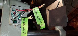
I deeply apologize for my impatience. See pics below. I have +/- wires from the motor and +/- wires from the power cord. Front and back of switch is shown. How do I connect the wires? Any help would be appreciated. Thank you all.

1.jpg2.jpg3.jpg4.jpg5.jpg
 

Attachments

  • 1.jpg
    1.jpg
    93.4 KB · Views: 58
OK, as you mentioned, you are obviously not very knowledgeable when it comes to electricity.

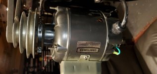
That looks like an AC motor, as dalmationgirl said, and so it doesn't have a plus or a minus.

It looks as if it is a 120VAC motor, so it will have a Hot and a Neutral wire, as does the cord that plugs into the wall.

Are you sure the cable with the White, Black, and Green is coming from the motor, and the one with what looks like Red, 2 Black, White, and Green is coming from the power cord?

Is that toggle switch that you show the wires connected to a reversing switch? Or....?

What are those things that are inline with the wires, one looks like it has 2 reds and a black, the other has a black, a brown, and a white. Are they capacitors? Any markings on them? The photo, without others from various angles, is pretty useless.

I can't read the model number on your shitty photo of the switch, either.

Sorry, man, but if you want help, you really need to do some more work, and get all the info out to us.

If you do, I'm sure we can help you hook it up.
 
You have a Line(black), Neutral (white), and Ground(Green)

The switch appears to be two pole. Make one side for Neutral and the other side Line.

Power in should be on top, motor wires on the bottom.
 
Like ziggy said above, the 2 wires to the cord go to the top of the switch, 2 screws on that end. The "motor" wires go on the other end of the switch. It will run no matter how you hook them up side to side but you could/should keep the power wire (black from power cord) in the power side of things all the way to the motor. Maybe the motor wiring tag will point out which terminal is neutral (white) and which is line power.
AC or Alternating Current, switches or "alternates" back and forth (between the black and white wires) 60 times every second, that is why it will work either way you wire it, best to do it right though.
 
Thank you all. With your help I have resolved the problem and the switch is working well. Very much appreciated.

I have another question for which I will post a new thread and will research and well document before I do.

Thank you all again.


Back
Top