What's new
What's new

Two straight edges and a collimator with no granite large enough.

Alex McGilton

Cast Iron
Joined
Apr 19, 2015
Location
Montreal, Canada
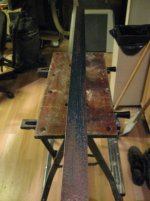
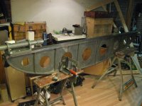
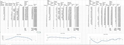
I hope the title describes my predicament. I have two camel backs that I intend to scrape straight to factory condition without access to a granite plate large or accurate enough. I got the 48 and 96 inch straight edges at auction in fairly good condition, immaculate scraped surface on both with visible wear on the ends of the small straight edge and non on the large one. See the first and third graph for the collimator results respectively. With the intentions of improving the two of them I started by scraping the small on to the large one over the long inclined section. What resulted was the second graph, slightly flatter but with a more wear resistant concave profile. Still have yet to fine scrape it should I decide to make it flatter then the large straight edge provides. The larger on I have yet to scrape but needs it more having a 0.00151" high crest. What I presume is that it was well scraped to an 8 foot B grade granite plate being permitted to have .002" of error.

The way that I had measured the entire flatness of the straight edge was to mount the collimator on the end, and having the mirror placed at the 1/4 point with the reading noted. The remaining 3/4 is measured before returning the mirror to the 1/4 point, inverted in direction with the collimator at the same noted measurement before measuring the remaining 1/4 was measured.

What I'm intending is to scrape down the middle of the larger camel back using only the small one for the rubbing and the collimator to check for flatness. My concern is that doing this I may obtain a twist in the large straight edge and have no way of observing or measuring this. Any thoughts on how to measure this would be appreciated. Would mounting a pair of levels both perpendicular to the straight edge be reliable enough to measure twist?
 

Attachments

  • IMG_3197.jpg
    IMG_3197.jpg
    95.1 KB · Views: 270
  • IMG_3204.jpg
    IMG_3204.jpg
    96.3 KB · Views: 204
  • IMG_3240.jpg
    IMG_3240.jpg
    95 KB · Views: 246
  • IMG_3243.jpg
    IMG_3243.jpg
    96 KB · Views: 270
  • brown and sharpe streaght edges 1.jpg
    brown and sharpe streaght edges 1.jpg
    99.1 KB · Views: 236
Come on down to balmy Vermont and buy this 4'X5" DoAll Inspection grade (Double A) stone from me. ;-)

It won't do 96" in one hitch, but near enough ;-)
 
Two things:-
1) A pair of levels will measure twist very well.
2) If you can modify the mounting of the mirror to replace the front long foot with a single circular one on the left, followed by one on the right side, you can measure the slope of the sides of the straight edge separately (provided the mirror is stable with an offset front foot...).
 
Instead of jiggery pokery, why not just rent time on a long enough surface plate. Or buy one? If you're near Montreal there's plenty of industry.

L7

On edit: I tried to resist saying this as everyone's circumstances are different, but please, please, make yourself a proper workbench. I can't imaging scraping anything being held in those wet noodle contraptions.
 
On edit: I tried to resist saying this as everyone's circumstances are different, but please, please, make yourself a proper workbench. I can't imaging scraping anything being held in those wet noodle contraptions.

I rather presumed that the wet noodle mounting was to eliminate any induce warp from the mounting system. The straightedge must be WAY stiffer than the stands. And as far as work platform versus test stand, so long as the noodles don't compromise the strokes in scraping and the whole contraption isn't walking across the shop as you try to scrape, what's the difference?

Dare I say "Different strokes ... "?
 
The graph is made in excel. The calculations came from page 11 onward from "Watts Microptic Auto-Collimator Instructions For Use" then interpreted for excel. Fell free to use it, but consider it a free beta. Check the work your self, I won't be held liable for an error my part or an incompatibility of equip.

To use
open zip in excel

First, enter the rise per arc-second for a given mirror carriage. It should be written on it otherwise. ( Rise ~= sin(1 arc-second)*distance of contacts ) for small angles only.

Second, enter the collimator results and leave the unused data points below blank. The "If measurement is Present" is necessary.

Edit: the old excel sheet has been replaced the user instructions are the same.
 
Last edited:
-CalG,
I don't have the space or funds to put a side for a larger plate. I will have to see if I can latter afford the time and money to go to the VT scraping class this spring.

-Mark Rand,
I was hoping for some insight on the two level option, given the short aspect a modest machinist level has the resolution, however since this is a vary small contact area how do I ensure I'm not reading erroneous readings from inconsistency of the level base.
I see what you mean by the three point mirror carriage reading one side at a time, but how do I interpret the data and isolate twist from the natural profile.

-lucky7,
I fear anyone with an 8 foot inspection plate won't let me near them if I told them I was putting paint down. While on the concern of cost, my intentions are to later scrape a lathe or milling machine with these camel backs. With enough funds I may well just buy new machinery and do away with scraping anything. SO instead I'm intending to "jiggery pokery" my may to having a pair of factory condition straight edges. Should I fail, I could easily sell them in a "as machined condition" for what I'm into them for.
Yes those wet noodles are a pain, and are too tall for anything other then inspection. I indent to take the doors off the near by bench and clamp to front face, seen in image 3197.

-TGTool,
It's just a quick setup good only for inspection.
 
My apologies. It took me all afternoon and some frantic re-checking but here is the edited data excel sheet.I tried entering the example from the Instructions For Use sheets and got a different plot. Now the sheet is fixed and I welcome scrutiny. Also the plot came out different as seen in the excel sheet, now both of the straight edges appear to be superb in their readings, almost too good to be true. with 48 inch now having 89 millionth flatness and the 96 inch being 535 millionth flat.
 

Attachments

  • autocollimator results.jpg
    autocollimator results.jpg
    108.5 KB · Views: 70
  • autocollimator graph (3).zip
    39.5 KB · Views: 23
Scary stuff, think I will stick with step printing my 4ft from the 3ft. Then use the 4ft to step print the 6ft.

One comment I would add, the SE in the photo's look very similar to the B&S castings discussed in another thread - I have one very similar which to date I have not managed to get a consistent set of readings / print from when inverted - either with a level or when trying to print 3ft sections. It is now back hanging from its end at the back of the que as I work through the heavier SE's. The small wooden handles do not lend themselves to 'stands' and even setting the SE up inverted with supports to stop it shifting & not introduce any forces to affect the face - still not a consistent print / reading. I dare say flipping and printing on a full size plate would resolve the matter. Does make me wonder how reliable they are long term..

In terms of twist - I found that as suggested in another thread - printing diagonally between lengthwise prints has helped keep me scraping evenly and not biasing one side or the other.

It is slow going though without a full size master plate to work from.

Keep up the thread - its all helpful stuff
Mat
 
don't think a modest machinist level has the resolution you need
I would want something like.0005 per division

And just to make things more complicated shouldn't the level be on the mirror carriage since twist will affect the height reading?

Would it be possible to add a line into your excel sheet for the level readings
 
don't think a modest machinist level has the resolution you need
I would want something like.0005 per division

The level setup in this case will amplify the readings. Suppose your level is 10" long with .001" per division. That means that if you put a .001" feeler gauge under one end the bubble will shift one division. That also means that halfway along the length you could only insert a .0005" gauge. Or, two inches from the end touching the surface you could only slip in .0002". Now placing the level crosswise on a straightedge with a 2" wide base, a .0002" deviation would shift the bubble a full division. And if you can estimate to half a bubble division, your 10" level, .001/div can read fairly easily a .0001" tilt in the surface.

So with a reasonably calibrated eyeball you should be able to read a few millionths as you move along.


Back
Top