What's new
What's new

RFQ - custom precision screw assembly

chris9911

Plastic
Joined
Jul 13, 2018
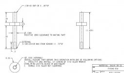
Due to the upload size limit, I've done a screen capture of the pieces and attached them here. I'm not looking for the cheapest, my priority is in the quality and speed. Thanks for your consideration.

I need 6 sets of this assembly. I need two quotes:
1. made with #6-40 thread on the shaft and the nut
2. thread pitch much greater than 40 and up to 220tpi.
 

Attachments

  • screw1.jpg
    screw1.jpg
    47.2 KB · Views: 294
  • screw1a.jpg
    screw1a.jpg
    14 KB · Views: 239
  • screw1b.jpg
    screw1b.jpg
    25.4 KB · Views: 240
  • screw1c.jpg
    screw1c.jpg
    10.8 KB · Views: 222
No matter...that idea of screen shots for posting worked out very well.

No zipped files to deal with, no tiny prints we (the older members) can't read.

very nice.
 
Due to the upload size limit, I've done a screen capture of the pieces and attached them here. I'm not looking for the cheapest, my priority is in the quality and speed. Thanks for your consideration.

I need 6 sets of this assembly. I need two quotes:
1. made with #6-40 thread on the shaft and the nut
2. thread pitch much greater than 40 and up to 220tpi.

The 6-40 thread is doable for sure, but 6-220?!?
 
So the "flexible" middle part has a .030 min wall but no max?
So it could be solid?
I will not touch the handful of other oops here.

I 'think' the first image takes care of that, defining model as master, and .01 tolerance

positive zero clearance fit?

not something I have heard of and doesn't google

220 tpi?

purty teeny
 
no oops, the drawing is an inspection drawing for acceptance. CAD is the master for mfg. Iges or stp files will be provided.
 
I 'think' the first image takes care of that, defining model as master, and .01 tolerance

positive zero clearance fit?

not something I have heard of and doesn't google

220 tpi?

purty teeny

no doubt this is a tough job. I am still interested in 6-40. 6-100+ will mean you got the job.
 
I 'think' the first image takes care of that, defining model as master, and .01 tolerance

positive zero clearance fit?

not something I have heard of and doesn't google

220 tpi?

purty teeny
Excellent question on the positive zero clearance. Rather than putting in 4decimal place inspection dimensions, I just care the titanium flex piece fits nice and tight with almost zero slack. Best way to describe it would be, press fit by hand while it can still rotate around the shaft. Does that answer your question? It's probably the most critical question asked so far. Thank you.
 
Excellent question on the positive zero clearance. Rather than putting in 4decimal place inspection dimensions, I just care the titanium flex piece fits nice and tight with almost zero slack. Best way to describe it would be, press fit by hand while it can still rotate around the shaft. Does that answer your question? It's probably the most critical question asked so far. Thank you.

Having done a fair amount of prototyping and instrument development work, this is often an area of subjective judgment in defining "almost zero slack". Your literal description of the fit is something I would call a "close slip fit", as "press fit by hand" is something pf an oxymoron. Having some numbers is always helpful when committing to actual part production. In my estimation, you are looking at something like +.0001/.0002" over the mating part diameter

Assuming that definition isn't a fatal obstacle, have you considered adapting off the shelf hardware for the application, such as the Thorlabs Extremely Fine Hex adjuster series of components? I think they offer 6-80, as well as M2.5 and M3 x 0.20 pitch, which would translate to about 127TPI. Could the shaft component be made from two pieces?

Do you have expectations of small radii in the internal corners of the flexure, or sharp corners?

Last, how close do the threads need to be to the shoulder, on the short end of the shaft part? This could relate to the above question about two-piece construction as well.

yes, thorlab and few other precision lab instrument companies do offer off the shelf adjuster sets with very high thread pitch, and I think its a fantastic idea for you to order the stock parts and turn those down as needed. .0001" clearance would be ideal, but I don't like dimensioning something that I cannot inspect. I would think the flexure piece has to be inserted into the shaft before cutting thread on the long side and certainly before pressing in the hex key. I want to receive a fully assembled assembly. My only verification on the clearance fit will be a 'slide and rotation' test to verify its near tight. A clearance gap at this joint will negate any type of precision I'm trying to achieve with the high thread pitch. What if you sent me two quotes. One with a standard 6-40 and 6-40+ using off the shelf items(something I might be able to provide). If you can make it with 6-40 with quick turnaround time, I would order 6 sets of that and another 6 to 12 sets of the 6-40+ version, since that might need some R&D time. To answer your other questions. The shaft can be broken in to two pieces if you want to use the off-the-shelf item. The nut shape can be anything as long as it has some kind of hex exterior shape. All entities not called out in the drawing is default profile and form tolerance of .01" which includes the radius. There is one critical inspection dimension that measures radius to radius on the flex part, you can machine it material safe and go slightly higher and start hand filing till you hit that dimension. I think you truly understand the design intent of this assembly, and would love to see your quote. Thanks.
 
I think you truly understand the design intent of this assembly, and would love to see your quote. Thanks.

Thanks for the vote of confidence, but I wouldn't be able to quote this right now for any sort of quick delivery. I am in the middle of a complex instrument development project that will likely run an additional couple of months longer from today. Perhaps the info we have discussed will help someone else quote the work for you. Good luck --
 
Thanks for the vote of confidence, but I wouldn't be able to quote this right now for any sort of quick delivery. I am in the middle of a complex instrument development project that will likely run an additional couple of months longer from today. Perhaps the info we have discussed will help someone else quote the work for you. Good luck --

Yes, thanks for chiming in, lots of useful information exchanged here.


Back
Top