Hi,
is that a normal or abnormal that i cannot mill a rectangular shape on my SQT lathe (without Y-axis). However, tried to drill 6 axial holes - the result is ok; and also radial slots are also ok and they are shown on the last photo.
Are you milling with a 90° tool holder (milling spindle is parallel to main spindle) or with a straight tool holder (milling spindle perpendicular to main spindle)?
Did you measure the X across the bolt-hole pattern?
(this would give the diameter of the bolt pattern and prove that it is square).
Based on the small amount of distortion (relative to the outside "radius" of the square part)
I would guess that you haven't accounted for the radius of the milling tool.
My reasoning is:
1) if you drill a hole with an axially aligned tool, you're drilling on the center of the tool (no radius compensation).
2) if you mill an OD with an axially aligned tool, you're milling on the far radius of the tool (1R radius compensation).
3) if you mill an ID with an axially aligned tool, you're milling on the near radius of the tool (-1R radius compensation).
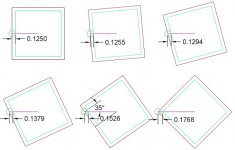
Regarding items 2 and 3, the machine will program a path based on the radius of the tool relative to the radius of the part. For a round part, this is easy addition of the two radii. For a square part, it's a little more complex as it requires dividing the tool radius by cosine of the spindle angle (the angular position of the square flange on your part).
Without radius compensation your square will be in error (radially) by an amount equal to the tool radius divided by the cosine of the spindle angle minus the tool radius. Don't try to make sense of that, just check out the diagrams I've drawn and it should be come clear. You don't necessarily NEED to know why, you can probably just enter the correct tool radius and the machine will compensate properly.
Look over these two diagrams, especially the one which is zoomed in.
These are drawn from the perspective of the spindle, looking through the workpiece toward the tail-stock.
The colors are as follows:
Green = cutting tool (1/4" diameter is shown)
Light Blue = Finished Profile of square flange on part.
Red = Tool Path (the centerline of the tool must follow this path)
Violet = Centerline of the X axis
Note: the light blue triangle is a right triangle which is represented in the formula shown.

